Car engines have been made in many formats; in-line. horizontally-opposed, V-block and so on. However so far as cars are concerned, probably the rarest type is the radial engine, in which the cylinders are arranged in a circle. In a four-stroke radial engine there has to be an odd number of cylinders to obtain a sensible firing order.
THE BALZER ENGINE & CAR
 |
| Left: The Balzer rotary engine & car: 1896
This design also uses a rotary engine; see the Adams-Farwell car just below as the only other example known at present. This is the sort of rotary engine where conventional pistons and cylinders rotate around a stationary crankshaft. Balzer is said to have built several automobiles in the 1890's but it is not currently known if he used his rotary engine.
The transmission is by a pair of rods driven by eccentrics attached to the rotating engine, which drive levers that alternately jam themselves against a central rotor fixed to the rear axle. It is all rather complicated, including a facility to 'declutch', and I don't think it is very practical, as it relies on friction.
The ring joining the cylinder is is fact an exhaust pipe, perforated with small holes to allow the escape of the exhaust gases. This was supposed to have a silencing effect.
Balzer worked with Charles Manly, who was associated with Samuel Langley and his unsuccesful Aerodrome flying machine.
Source: US patent 573,174 granted to Stephen Balzer in 1896
|
 |
| Left: The Balzer rotary engine & car: 1896
These diagrams show the peculiar transmission system. I would have thought the car would move forward in a series of jerks, if indeed it moved at all.
No evidence has been found so far that a rotary-engined car was actually built.
Source: US patent 573,174 granted to Stephen Balzer in 1896
Many thanks to John Beck for drawing this patent to my attention.
|
 |
| Left: The Balzer rotary engine & car: 1896
This diagram of a three-cylinder rotary engine comes from the same patent as the diagrams above. The cylinders are aligned with the crankshaft in the usual way. Note the annular exhaust pipe with perforations.
Source: US patent 573,174 granted to Stephen Balzer in 1896
Many thanks to John Beck for drawing this patent to my attention.
|
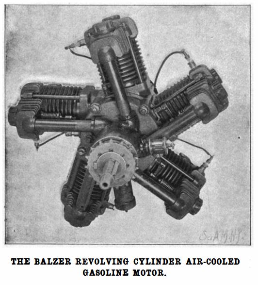 |
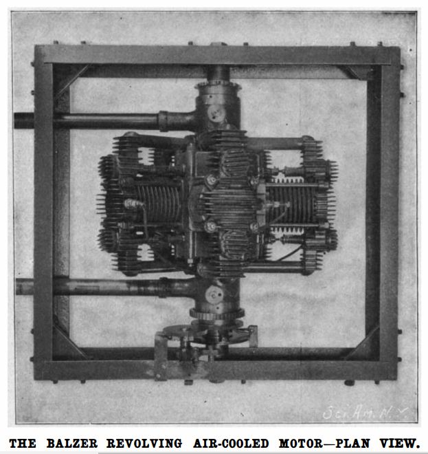
| Left: The Balzer 5-cylinder rotary engine: 1902
Note that almost every radial or rotary engine had the cylinder axis aligned with the centre of the crankshaft; so did the Balzer 3-cylinder engine shown just above. This engine apparently did not. The photograph was published 6 years after the 1896 patent, and Balzer may have come up with another unconventional drive system.
Source: Scientific American article 1902-03-01-v86-n09
Many thanks to John Beck for drawing this engine to my attention.
|
 |
| Left: The Balzer 5-cylinder rotary engine: 1902
This picture of the 5-cylinder engine mounted in a frame shows that Balzer had reconsidered his exhaust arragements, probably because the perforated-pipe method proved intolerably noisy. It also unwittingly shows a fundamental problem with rotary engines; both induction and exhaust had to pass through a hollow crankshaft, and the size of the openings limited the maximal gas flow.
Source: Scientific American article 1902-03-01-v86-n09
Many thanks to John Beck for drawing this engine to my attention.
|
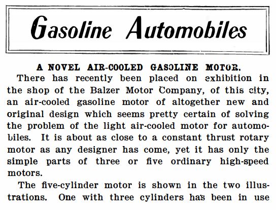 |
| Left: The Balzer 5-cylinder rotary engine: 1902
This is the first part of a Scientific American article in an issue called 'The Automobile and Outing Number'. Nowadays 'outing' means something rather different. More soon.
Source: Scientific American article 1902-03-01-v86-n09
|
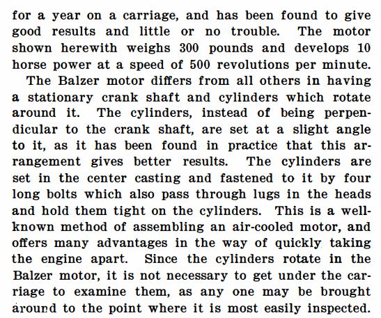 |
| Left: The Balzer 5-cylinder rotary engine: 1902
The next part of the article confirms that the cylinder axes were not aligned with the centre of the crankshaft; but it gives no clue how this can 'give better results'. Puzzling.
Source: Scientific American article 1902-03-01-v86-n09
|
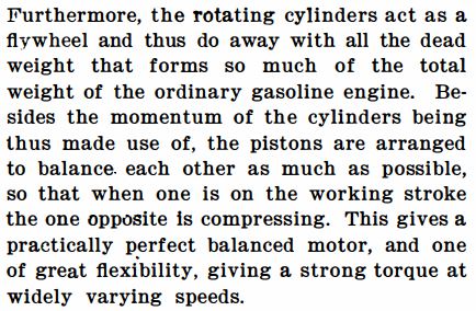 |
| Left: The Balzer 5-cylinder rotary engine: 1902
Here the main (and possibly only) advantage of the rotary engine is explained; since the whole engine rotates there is no need for a heavy flywheel.
Source: Scientific American article 1902-03-01-v86-n09
|
 |
| Left: The Balzer 5-cylinder rotary engine: 1902
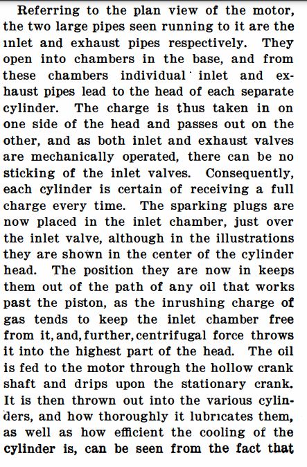
Here we learn that the inlet and exhuast valves were both mechanically operated, as opposed to having an 'automatic' inlet valve controlled simply by a spring, which opened on the induction stroke when the cylinder pressure fell below that of the atmosphere. Such inlet valves were simple but gave poor cylinder filling; the spring had to be weak to allow adequate induction, but was then liable to sticking open, bringing the engine rapidly to a stop. This is noted in this part of the article.
Splash lubrication was used rather than a pressurised lubrication system, and one wonders how effective it was.
Source: Scientific American article 1902-03-01-v86-n09
|
 |
| Left: The Balzer 5-cylinder rotary engine: 1902
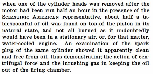
This part is puzzling. Having half a tablespoon of oil on top of the piston doesn't sound right to me. Why wasn't it burnt?
Source: Scientific American article 1902-03-01-v86-n09
|
 |
| Left: The Balzer 5-cylinder rotary engine: 1902
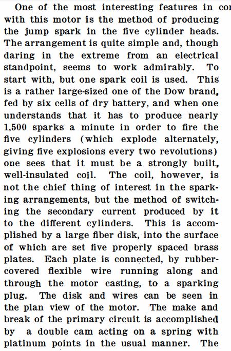
An explanation of the ignition system. I wouldn't want to buy a car that was '...daring in the extreme from an electrical standpoint...' under any circumstances.
Source: Scientific American article 1902-03-01-v86-n09
|
 |
| Left: The Balzer 5-cylinder rotary engine: 1902
I'm not too sure about the practicality of ball-and-socket joints on the connecting rods.
Source: Scientific American article 1902-03-01-v86-n09
|
 |
| Left: The Balzer 5-cylinder rotary engine: 1902
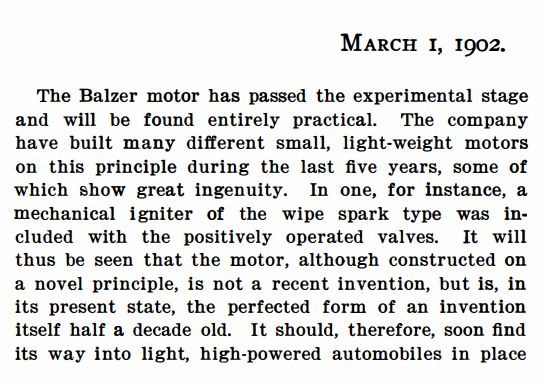
Some wholly unjustified optimism here.
Source: Scientific American article 1902-03-01-v86-n09
|
 |
| Left: The Balzer 5-cylinder rotary engine: 1902
The final part of the article. Despite its confident assertions, we are sill using water-cooled engines 124 years later.
Source: Scientific American article 1902-03-01-v86-n09
|
THE ADAMS-FARWELL CAR
The Adams-Farwell car was very unusual. Its inclusion here would make you assume it had a radial engine; in fact it had something much rarer; a rotary engine. This is nothing to do with Wankels but instead refers to radial engines in which the crankshaft is stationary but the cylinders rotate around it.
 |
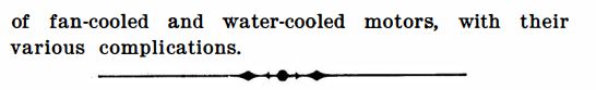
| Left: The Adams-Farwell car: 1906
Between 1898 and 1907, the Adams Company manufactured fifty-two automobiles that featured innovations like fuel injection, supercharging, and automatic control of ignition timing.
The car was probably the first in the world (but see above) to be powered with an air-cooled rotary engine, which was mounted at the rear of the car ahead of the back axle. The engine was mounted with its crankshaft vertical, and so the engine spun in a horizontal plane.
This is the only remaining Adams-Farwell car; you can read about its history here and here and here. The car is fully operational and on 21st August 2011 it won the prestigious Charles A. Chayne Trophy at the Pebble Beach Concours d'Elegance. The car is in the National Automoble Museum.
Thanks to Bill Godwin for reminding me about this car.
|
 |
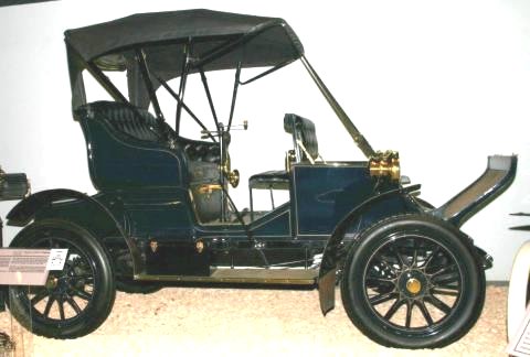
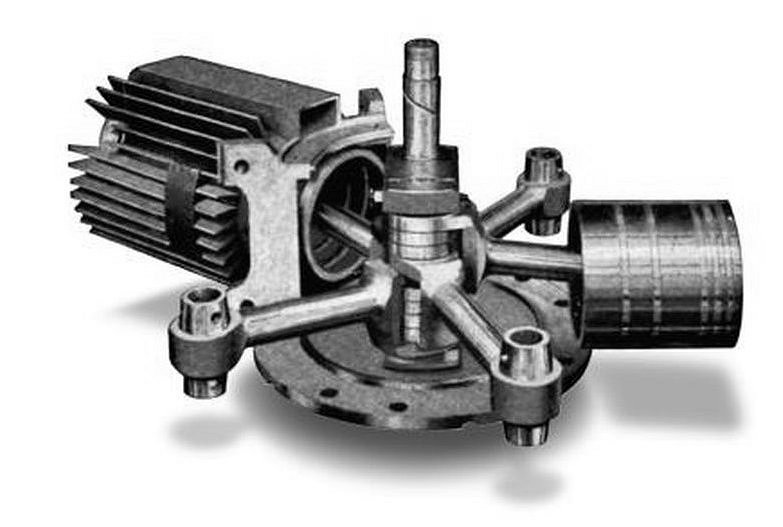
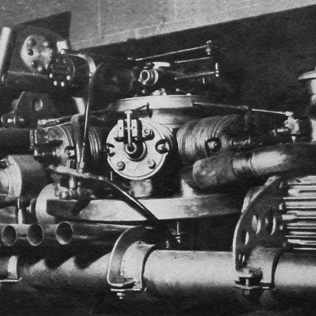
| Left: The Adams-Farwell engine: 1906
The engine in the Adams-Farwell car, one of only three engines in existence. It was four-stroke design and was made in both three and five-cylinder versions. A rotary (or radial) engine must have an odd number of cylinders to get a sensible firing order. The advantages claimed were that no heavy flywheel had be fitted as the engine was its own flywheel, and there was no need for cooling fans, etc.
However, a rotary engine does present some engineering challenges; notably that the inlet and exhaust ports and the spark plugs are whizzing round at engine speed. The inlet ports are connected to the non-rotating carburettor (to the left of the yellow cylinder on top of the engine) through a rotating joint, and the fuel air mixture reached the inlet valves through the flat boxes on top of the cylinder. In some versions of the engine the exhaust just came directly out around the exhaust valve, which must have been very noisy; the engine shown here has stub exhausts attached to the side of the cylinders, presumably to cut down the noise a bit. It is clear that connecting up five exhaust ports with a non-rotating silencer system would be enormously difficult.
Pic source: Pebble Beach Concours d'Elegance 2011
|
The sparkplugs present less of a problem as there are five contacts mounted near the engine centre, which connect with the red sector-shaped thing to the right of the yellow cylinder. This sector is connected to the ignition system by the wires going out of picture at top right. This works like a distributor; given the high voltage the contact does not actually need to rub on the sector (it would soon wear) but just be close enough for a spark to pass without undue loss of voltage.
 |
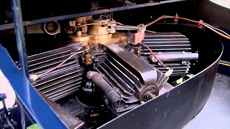
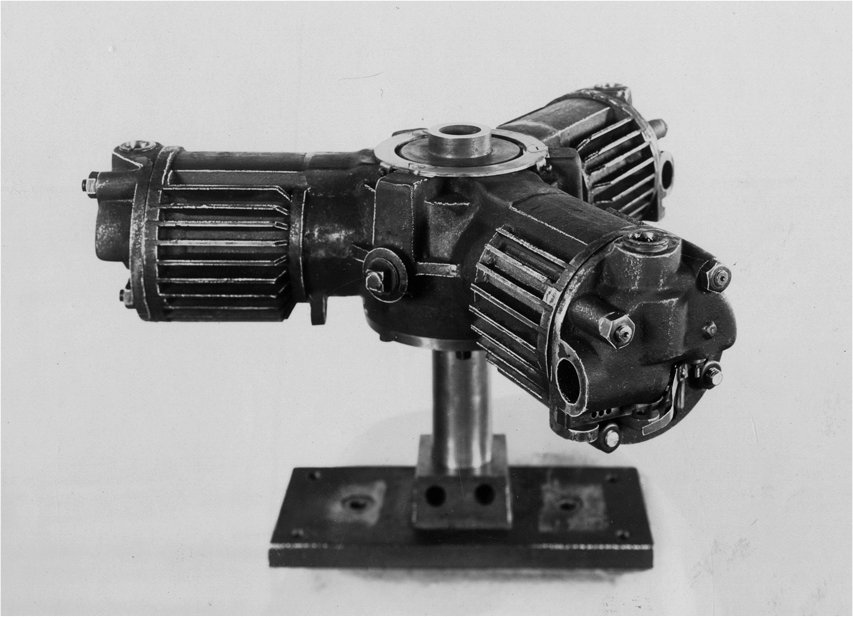
| Left: The Adams-Farwell engine: 1906
This Adams-Farwell engine is one of three in existence. This example is in the Smithsonian National Air & Space Museum.
The output shaft can be seen at bottom right
For some reason, this engine has no cooling fins.
|
 |
| Left: The Adams-Farwell engine: 1906
The internals of the engine. The five connecting rods each have their own connection to the crank-pin.
This picture shows each piston has having five rings, which somehow show on the inside of the piston. The engine cross-section below shows four rings per piston, fitting into conventional ring grooves.
|
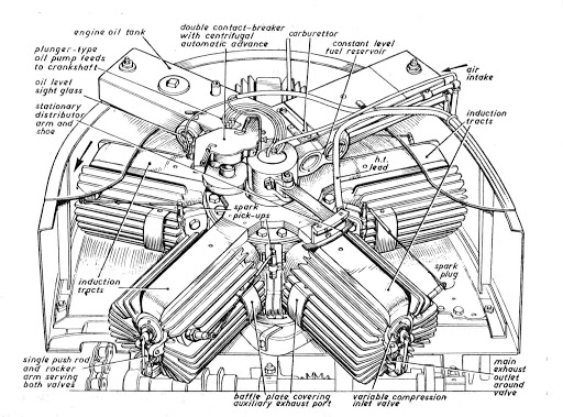 |
| Left: The Adams-Farwell engine: 1906
The parts of the Adams-Farwell rotary engine.
Note that both valves are operated by one push-rod underneath the cylinder, there is a 'variable-compression' inlet valve, and there are no exhaust stubs; the exhaust escapes around the exhaust valve.
From one point of view, this is going to be a difficult engine to work on; how do you do a compression test when the whole engine is whirling about? On the other hand, as an early reviewer pointed out, to get access to any cylinder you simply had to turn the engine round.
Source: unknown
|
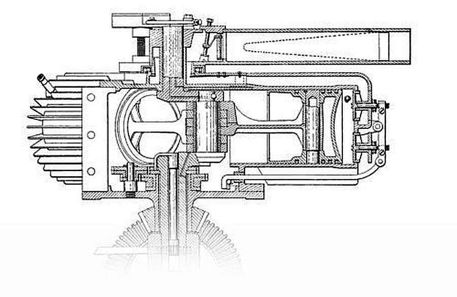 |
| Left: The Adams-Farwell engine: 1906
This section of the engine shows the non-rotating air intake pipe at top right; the dotted thing appears to be an air filter. At lower right a single circular cam with a follower on its inside face operated the two valves via a curved rod. They do not look like conventional poppet valves.
There is no possibility of having different timings for the inlet and exhaust valves, which makes one wonder what effect that had on engine efficiency.
At the bottom is the bevel gearing to the output shaft.
Source: unknown
|
 |
| Left: Three-cylinder Adams-Farwell engine: 1896
This early three-cylinder engine. On the back of the photograph has been typed: "Number two. 4" bore, 4" stroke, ignition make and break. Built in 1896, was never placed in a car."
The design of the cylinder-head is completely different from that of later engines.
Source: Detroit Public Library Collection
|
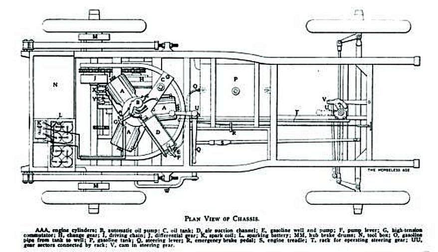 |
| Left: The Adams-Farwell chassis: 1906?
This appears to be an early version of the car, with a three-cylinder engine and tiller steering. The engine output shaft droves the rear axle via a chain, and a differential gear J. There are drum brakes M on the rear, but no brakes are visible at the front. Note the large battery required just to run the coil ignition system. I don't see any provision for a starting handle.
Source: The Horseless Age, date unknown at present, but pre-1910 as the advert below shows steering wheels.
|
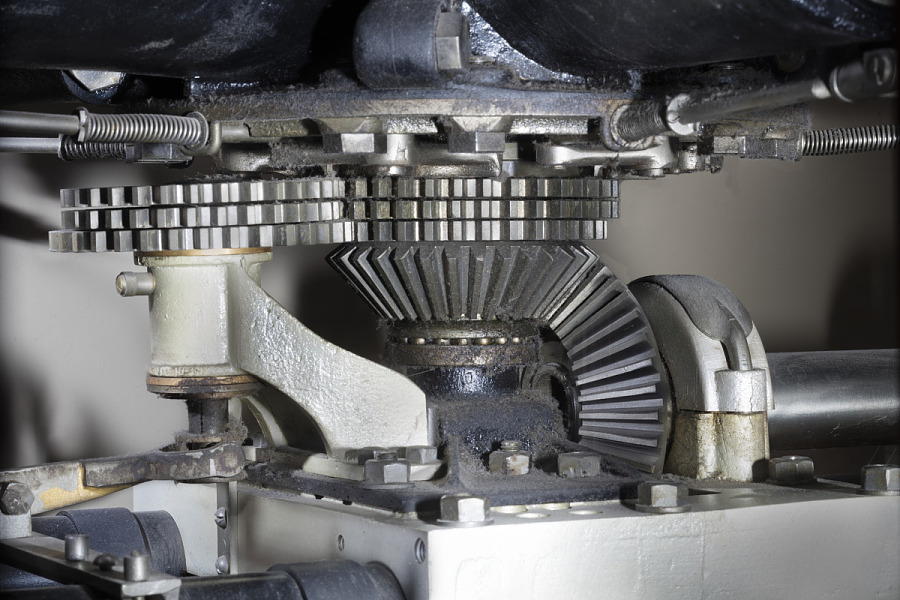 |
| Left: The Adams-Farwell engine: 1906
The bevel gears that connected the vertical engine crankshaft with the horizontal output shaft. The spur gears above are believed to be part of the gearbox, but this is not yet confirmed.
Source: Smithsonian National Air & Space Museum.
|
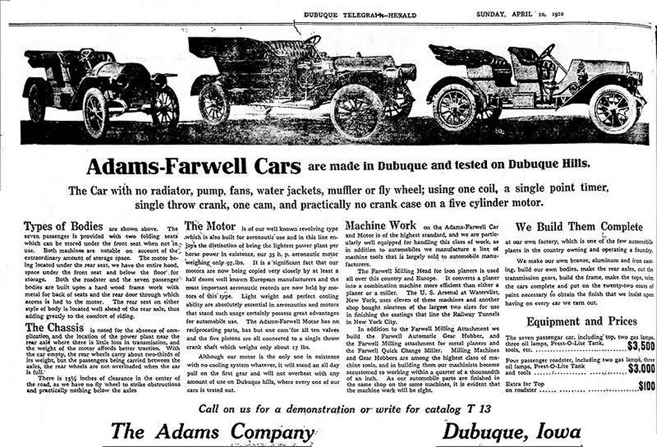 |
| Left: Advertisment for the Adams-Farwell car: 1906
The advert claims that the 'motor' developes 25 HP for a weight of only 97 pounds.
"The Adams-Farwell Motor has no reciprocating parts, has but one cam for all ten valves and the five pistons are all connected to a single-throw crank shaft which weighs only about 17 pounds." No reciprocating parts? What about the pistons?
Note that the cars now have steering wheels rather than tiller steering.
|
THE NORTH-LUCAS CAR
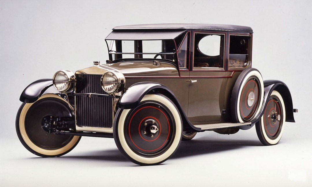
Colin Lucas was a well known English architect in the nineteen-twenties and thirties. He collaborated with Oliver North to build this aerodynamic car. It had a single headlight, and a boat-shaped body with a roof of translucent canvas.
There are some biographical details on what I think is the right Colin Lucas here but there is absolutely no mention of a car.
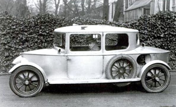 |
| Left: The North-Lucas car: 1922
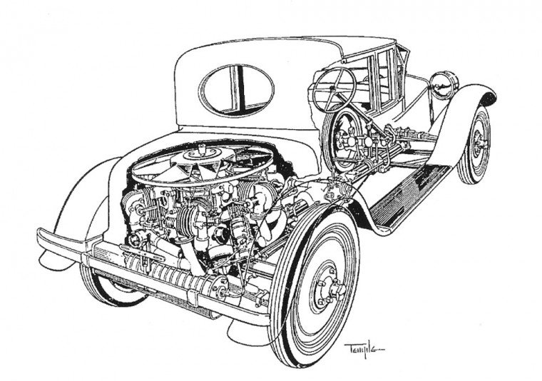
This looks a bit like streamlining but it probably isn't very aerodynamic. The vertical sides and near-vertical windscreen suggest that the drag coefficient would not have been impressive. The rear-engined prototype had a top speed of 55 mph, which doesn't seem very quick from a 1.5-litre engine.
For those (excusably) in doubt, the front of the car is at the left. There is a large intake for the air-cooled engine just behind the spare wheel.
|
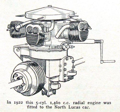 |
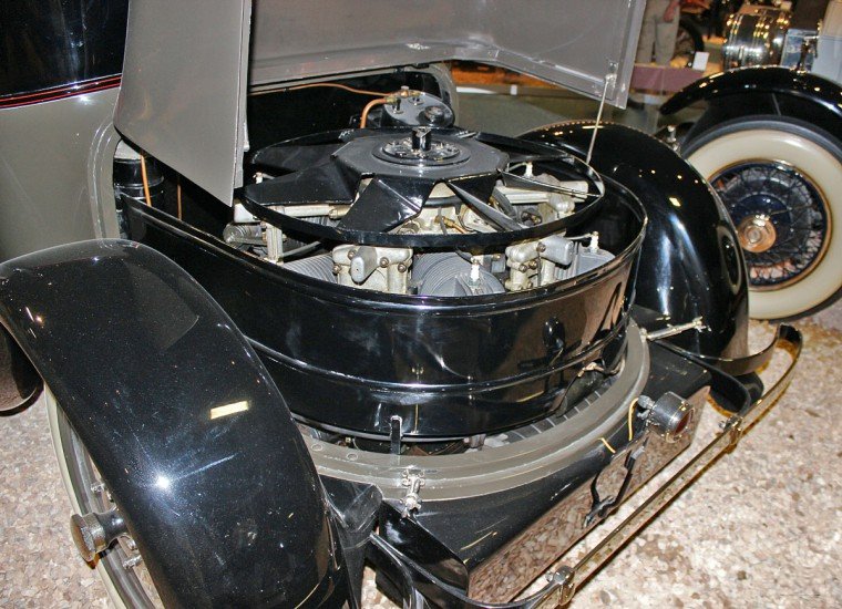
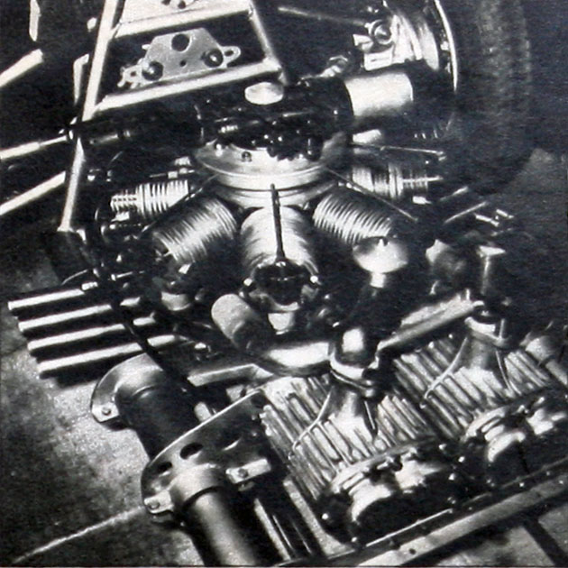
| Left: The 5-cyinder engine of the North-Lucas car: 1922
The engine sat on top of the transmission; there were finned inboard brakes and the suspension was by swing-axles.
The induction manifolds vanish under the flywheel; was the carburettor there? Note that the exhaust manifold is not shown. An aeroplane radial engine could use stub exhausts, but a road car would have to have the exhaust from the five cylinders collected into a silencer, and this must have been a serpentine piece of plumbing.
It has been remarked that the fan-blades on the flywheel are well-situated for slicing off the fingers of anyone examining the engine when it was running.
|
THE JULIAN SPORT COUPE
Julian Brown inherited a $2.5 million fortune from his industrialist father, and spent much of it on developing engines and cars that never reached production.
 |
| Left: The Julian sport coupe: 1927
Julian Brown designed the aluminum body, which was then constructed by the
Fleetwood Metal Body Co. It was finished and mounted on the backbone chassis in 1925.
|
 |
| Left: The Julian sport coupe: 1927
The steel backbone frame consisted of a 4.5-inch central tube, with two 2.0-inch crossmembers fixed to it at front and back. The cross-members supported the aluminum five-passenger coupe body.
|
 |
| Left: The Julian sport coupe: 1927
The radial, six-cylinder engine was set horizontally at the rear, as in the North-Lucas car. The cylinders were set 120 degrees apart. It appears to have been a four-stroke engine so it is unclear how the cylinder firing order could be arranged with an even number of cylinders. The crankcase was aluminum. Bore and stroke were 3.375 x 5.0 inches giving a displacement of 268.4 cu-in. (4398 cc) The power output was said to be 60 HP at 2500 rpm. The compression ratio was a modest 4.8 to 1.
It is currently unclear how the cooling air got into the engine compartment. Presumably it exited downwards.
|
More information can be found at The Old Motor.
 |
| Left: The Julian sport coupe: 1927
This contemporary image, sadly of poor quality, shows the rear engine and part of the chassis. Note part of the exhaust manifold leading into the cylindrical silencer.
|
THE ROHRBACH CONCEPT
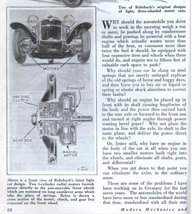 |
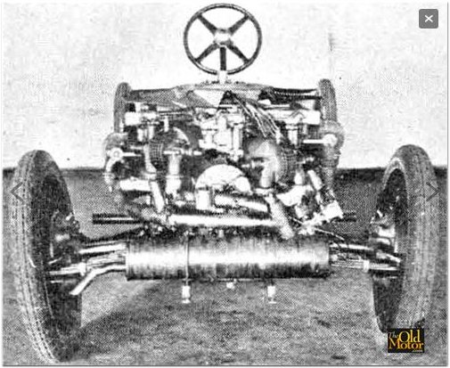
| Left: The Rohrbach concept put a radial engine in each wheel: Modern Mechanix 1931
There are, I suggest, some obvious problems here. There are two engines to go wrong and I suspect driving on one engine is not going to be feasible. The engines are unsprung weight and will cause some serious handling problems. The spark-plugs and ignition system are shielded from the elements by a casing; the ignition etc may be kept dry, but it is not clear how air is going to get to the air-cooled cylinders. It seems Rohrbach believed that his special engines would not need any cooling. (See just below)
There is the obvious problem of feeding the petrol supply, and the controls for throttle, clutch and gearbox, through a rotating bearing. It would certainly be interesting if the two gearboxes got out of sync.
In short, this is a daft idea. However that never stopped magazines like Modern Mechanix publishing them. And why not? They have a certain entertainment value.
From Modern Mechanix May 1931, p84
|
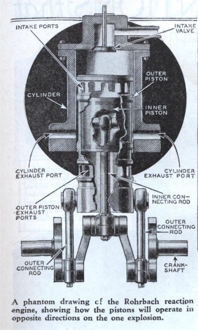 |
| Left: The Rohrbach engine: Modern Mechanix 1931
Like many inventors, Rohrbach thought it a good plan to use as many new ideas as possible. He had convinced himself that the faster a piston moved, the less likely it was to overheat, and so built an engine where the combustion space was between two moving pistons rather than the piston and the cylinder. Therefore, he reasoned, no engine cooling was required. Simples!
The two pistons were driven from one crankshaft as shown in the picture. A single-cylinder prototype was built, but no details of its performance were disclosed. There is no sparkplug as the inventor claimed it used compression ignition, which seems to point to some sort of Diesel fuel. Rohrbach claimed his engine used half the fuel of a conventional engine; not very plausible.
Who was Rohrback? A first thought was Adolf Karl Rohrbach, who joined the Zeppelin Company in 1914, and went on to be involved in the design of large R-Plane (Riesenflugzeuge, or giant aircraft) bombers.
However, the real answer is Hans Rohrbach of Hamburg, Germany, who is known to have been involved in car design.
|
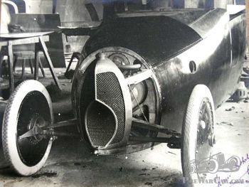 |
| Left: A Hans Rohrbach car: 19??
This car was built by Hans Rohrbach. In 1922 he founded the Leichtfahrzeugb au-Gesellschaft for the exploitation of his patents like a unit-body (monococque?) car. He is actually best known for the Modern Mechanics article from 1931. One version of the car used a NAG 8/24 PS engine.
It is difficult to describe this car as beautiful or stylish, with its very odd radiator that looks like a gaping mouth.
In 1948 he showed an updated design of his three-wheeler as a model at the Leipzig fair.
|
THE PORSCHE 12 CAR
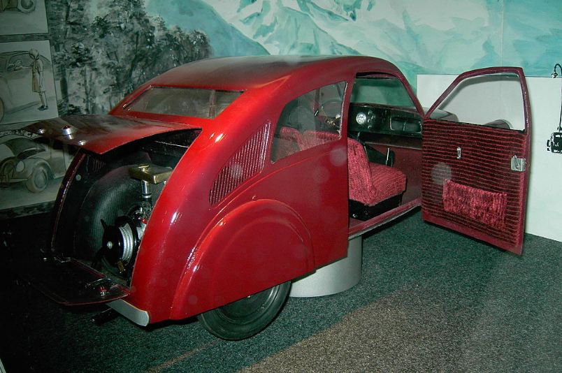 |
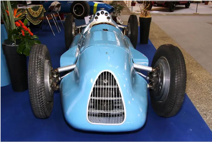
| Left: A replica of the Porsche 12: 1931
The Porsche 12 was intended as an 'everyman' car (like the Volkswagen was supposed to be) and was designed by Ferdinand Porsche for the Zundapp company. Only three prototypes were built, and all were lost during WW2. The Citroen 2CV, introduced in 1948, was a similar project, but went on to be very successful. The 2CV had a flat-twin engine driving the front wheels. I once had one.
The Porsche 12 has a Wikipedia page.
Many thanks to Bernd F for drawing this car to my attention.
|
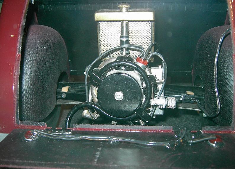 |
| Left: A replica of the Porsche 12: 1931
The engine was a Z�ndapp five-cylinder radial of 1193 cc with water cooling. Not much of it is visible here.
Porsche wanted to use an air-cooled flat=four engine (as fitted later to the Volkswagen) but unsurprisingly Zundapp wanted to use one of their own engines. Zundapp were basically a motorcycle builder and what they were doing making radial engines is currently unclear.
The silver thing behind the engine is presumably the radiator.
|
THE STAPP LAND SPEED RECORD CAR
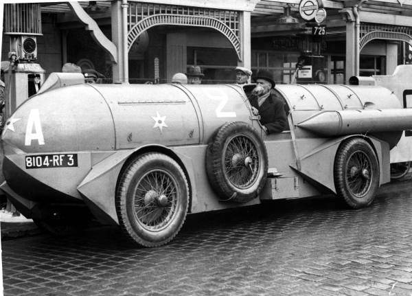 |
| Left: The Stapp Land Speed Record car: 1932
The Stapp car was a Land Speed Record (LSR) contender powered by three 9-cylinder Bristol Jupiter air-cooled radial engines; or was it?
Ren� Stapp was a racing driver rather than an automotive engineer, which may explain some of the contradictions in the existing information about the car. At the time the LSR stood at 253 mph, set by Malcom Campbell in the Campbell-Napier-Railton Blue Bird in Febuary 1932.
The 1932 Jupiter engine produced 440 HP, so the total horsepower available would have been 1320 HP. However Stapp claimed he was going to use a petrol-electric transmission capable of carrying only 800 HP; even that would have been very heavy and complicated. This is just one of the contradictions in this project.
The car itself was called Jupiter, but there actually is no evidence that the car was ever fitted with one radial engine, let alone three. Stapp was testing it on a French beach called La Baule when it caught fire. (he escaped) and it has been suggested many times that the car was deliberately destroyed to prevent its exposure as a hoax. It is hard to see how any fire, however fierce, could destroy all traces of three great big radial engines. My own objection is that Jupiter engines were large, and from the photographs the only possible way three engines could have been fitted in the car was in-line, which would cause massive problems in getting enough cooling air to them; the air intake visible at the lower front of the car does not look big enough for one Jupiter, let alone three.
My correspondent Stu Riegel has the following to say:
"A quick look at the Jupiter engine reveals its overall diameter is 54.5 inches. A 1930 Voisin C20 (not sure if this was the actual Voisin chassis used, but it's a big 'un) measures 59.8 inches track width (typically but not always measured center to center of the tire). If one assumes a 7-inch tire typical of large cars of the period, that leaves
52.8 inches between the tires, not enough for even an unshrouded Jupiter."
"The pictures of the Stapp car show the full width of the wheels are clearly outboard of the central cylinder, and by a healthy margin. It's especially clear in the video.(although it seems to produce enough smoke for three Jupiters) There just isn't room."
|
|
Thanks to Mathieu Maury for drawing this car to my attention.
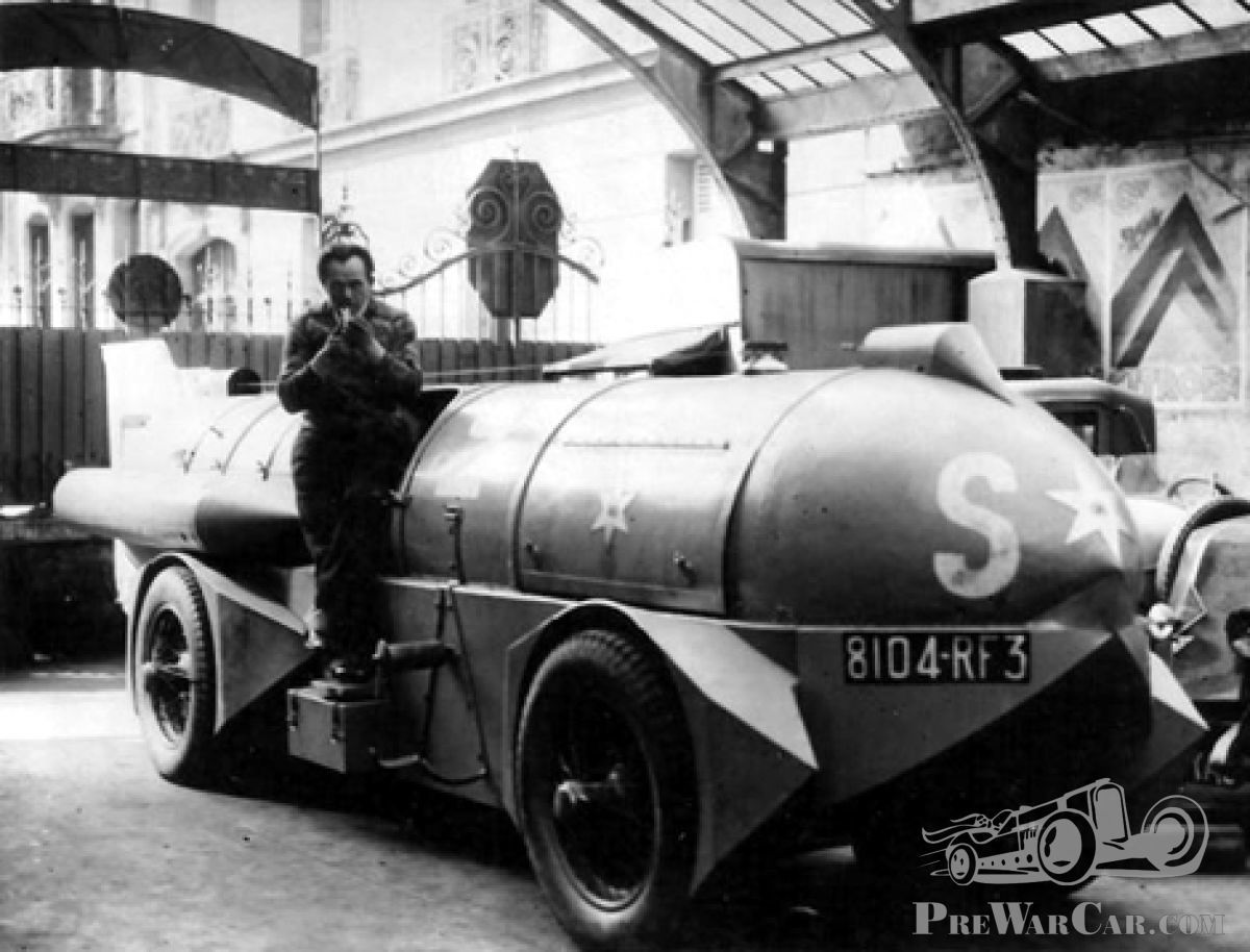 |
| Left: The Stapp Land Speed Record car: 1932
The Jupiter was constructed just outside of Paris, apparently based on a Voisin chassis. It was apparently put about that the Voisin engine was left installed to act as a starter motor for the three big radial engines. That makes some sort of sense, but it is very hard to see how three big radials and the existing engine could all be fitted into the body.
Things got a bit weird after this because Stapp then claimed he was going to convert the three Jupiter radial engines into gas combustion turbines by removing the pistons from them. The engines would then allegedly give 800 horsepower each, power going to all four wheels via an electric transmission. It (I hope) hardly needs saying that such a process would have been utterly impossible.
There is more information here.
Ren� Stapp has a short Wikipedia page.
He should not be confused with Colonel John Stapp, a pioneer in studying the effects of g-forces on human beings.
|
 |
| Left: The Stapp Land Speed Record car: 1932
There is a video of the car being driven around the streets of Paris on YouTube. It has often been suggested that the car was running on its original Voisin engine for this trip.
At around 0:13 Stapp can be seen wearing a sort of flying-helmet as he fuels the car. It is he who drives it, from the opposite side of the car from the man in the dark coat, whose identity is unknown.
|
THE MEYERS CAR: 1932
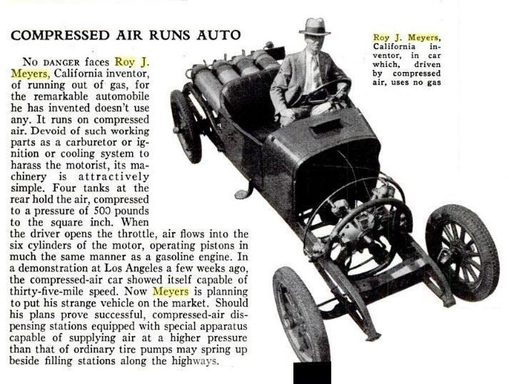 |
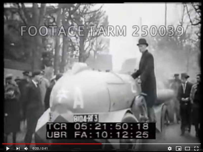
| Left: The Roy J Meyers Air car: 1932
The most important thing about the Meyers car was not the radial engine, but the compressed-air propulsion; note the four gas cylinders at the back of the car. This photo gives a good view of the six-cylinder radial engine. So far as I can see there are no fins on the cylinders to combat the icing that occurs when you cool air by expanding it.
Another important thing about the Meyers car was that it was almost certainly a perpetual-motion fraud. Roy J Meyers had a colourful history, which included a 3-1/2 year sentence in the Arizona state prison at Florence; what for does not seem to have been recorded.
There is more information in the compressed-air vehicles gallery.
From Popular Science for Jan 1932, p58
|
THE TROSSI-MONACO RACING CAR
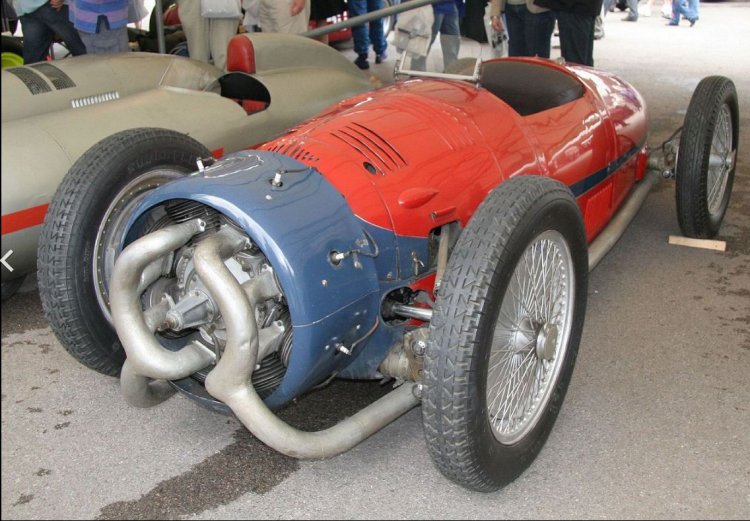 |
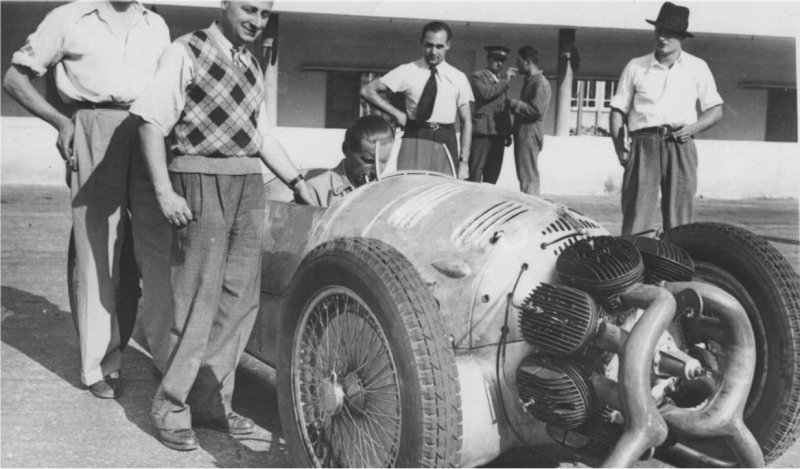
| Left: The Trossi-Monaco racing car: 1934
Count Carlo Felice Trossi was both a racing driver and a car constructor. As a racing driver he raced for Alfa Romeo, Mercedes-Benz, and briefly for Maserati. He won the 1947 Italian Grand Prix and the 1948 Swiss Grand Prix- but not in the car shown here.
The project was begun by engineer Agusto Monaco; he persuaded Fiat to test the engine at their Lingoto plant, but its poor performance and reliability led to Fiat withdrawing their support. Agusto then persuaded Count Trossi that the project was worthwhile, and this remarkable radial-engined car was built in Trossi's ancestral castle at Gaglianico, outside Biella in Northern Italy. It was designed to meet the 1934 Grand Prix formula.
The car looked very much like an aeroplane engine nacelle with the propellor missing, and created a sensation when it was unveiled. The engine was a two-stroke design with sixteen cylinders, arranged in pairs with one cylinder behind the other; each pair had twin pistons but a shared combustion space and single spark-plug. Its capacity was 3.982 litres. In a bay behind the engine were two M160 Zoller superchargers drawing from two Zenith carburettors.
The output of this amazing engine was claimed to be 250 BHP at 6000 rpm, which sounds impressive until you compare other contemporary racing cars such as the 3.8 litre Alfa-Romeo, (305 BHP) the 5-litre Auto-Union (375 BHP) and the 4-litre Mercedes. (430 BHP) The 1934 Grand Prix formula introduced a maximum weight limit of 750 kg, but there was still no limit on engine capacity; that was not introduced until 1938.
The Trossi-Monaco racing car is in the Museo dell'Automobile, Turin.
|
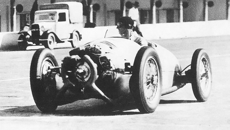 |
| Left: The Trossi-Monaco racing car under test in 1934
The car had a front/back weight distribution of 75:25, because of the massive engine mounted forward of the front wheels, and must have been interesting to drive.
Note that here the Townend ring around the engine is not in place; possibly this was a attempt to improve the cooling. Normally Townend ring manages both to reduce drag and improve air cooling, but here it does not seem to have helped.
Tests showed that engine was very prone to overheating; the exhaust manifolds masking the cylinders would not have helped. It also destroyed spark plugs rapidly. The car was clearly not race-worthy, and it never appeared at a Grand Prix race.
|
 |
| Left: The Trossi-Monaco racing car: 1934
With the Townend ring removed. The ribbed thing is one of the two Zoller superchargers.
|
 |
| Left: The Trossi-Monaco racing car under test in 1934
With the Townend ring removed.
|
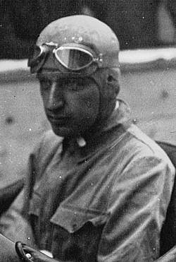 |
| Left: Count Carlo Trossi at the 1934 Grand Prix
Carlo Trossi is pictured looking thoughtful at the 3rd June 1934 Grand Prix at Montreux, Switzerland.
|
RADIAL-ENGINED FIGHTING VEHICLES
Several USA fighting vehicles were powered by air-cooled radial engines, because they were powerful for their weight. They were also available and thoroughly tried. One of the alternatives was the mechanical nightmare called the Chrysler Multibank, essentially five 6-cylinder engines mounted on the same crankshaft, giving a very heavy 30-cylinder engine which only produced 370 HP at 2400 rpm.
I am aware that a tank or a self-propelled gun is not strictly speaking a car, but this seems like a good place for the material.
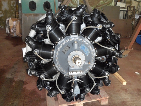 |
| Left: The Continental R975 radial engine: 1939-1950s
The Continental_R-670 was a 7-cylinder four-stroke radial aircraft engine of 11,000 cc displacement, giving from 210 to 240 HP at 2,200 rpm. It was used in the M1-Combat-Car and the M2 light tank, and a couple of other vehicles.
When greater power was required, The USA turned to the Wright R-975 Whirlwind, a 9-cylinder air-cooled radial engine running on petrol. Its displacement was about 16,000 cc and the power output in the range 300 to 450 HP at 2,400 rpm. The versions used in tanks etc were built by Continental under licence. The engine remained air-cooled, and cooling air was provided by a fan on the output shaft and appropriate shrouding around the cylinders.
The Continental-built R-975 was used in:
plus at least four other less-known allied fighting vehicles
|
THE GUIDOBALDI RACING CAR
 |
| Left: The Guidobaldi car: 1956
This racing car designed by Francois Guidobaldi was principally built to demonstrate a suspension system that caused the chassis to lean into bends rather than follow the dictates of centrifugal force.
The car is currently in the private collection of David Humbert, who has had it completely restored.
|
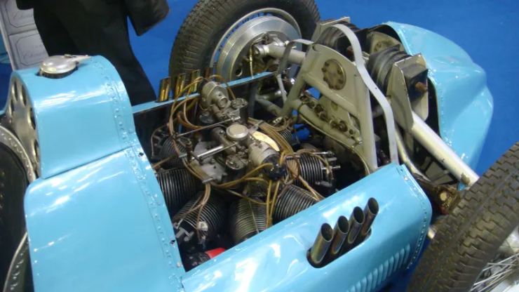 |
| Left: The radial engine of the Guidobaldi car: 1956
The Guidobaldi suspension system required the centre-of-gravity of the car to as low as possible, so a radial engine with its flat format was chosen. It was mounted at the rear of the car.
Guidobaldi designed the engine himself, coming up with a two-stroke, dual ignition, twin supercharged, air-cooled, 8-cylinder radial engine. Its capacity was 1500cc and so met the contemporary Grand Prix regulations which permitted either 4500cc unsupercharged or 1500cc supercharged engines. Fed by double Roots superchargers (originally from a Bugatti) the engine produced 180 HP at 6500 rpm.
The car was never raced.
|
 |
| Left: The radial engine of the Guidobaldi car: 1956
Just above the engine can be seen the distributor, with skew-gear drive from the crankshaft.
In the foreground are the two Roots superchargers. It is not currently clear how they were driven.
|
 |
| Left: The radial engine of the Guidobaldi car: 1956
|


