Hemispherical Drive

Gallery opened 24 Sept 2020

Page updated: 10 Oct 2020

HOG drive added
Back to Home PageBack to The Loco Index

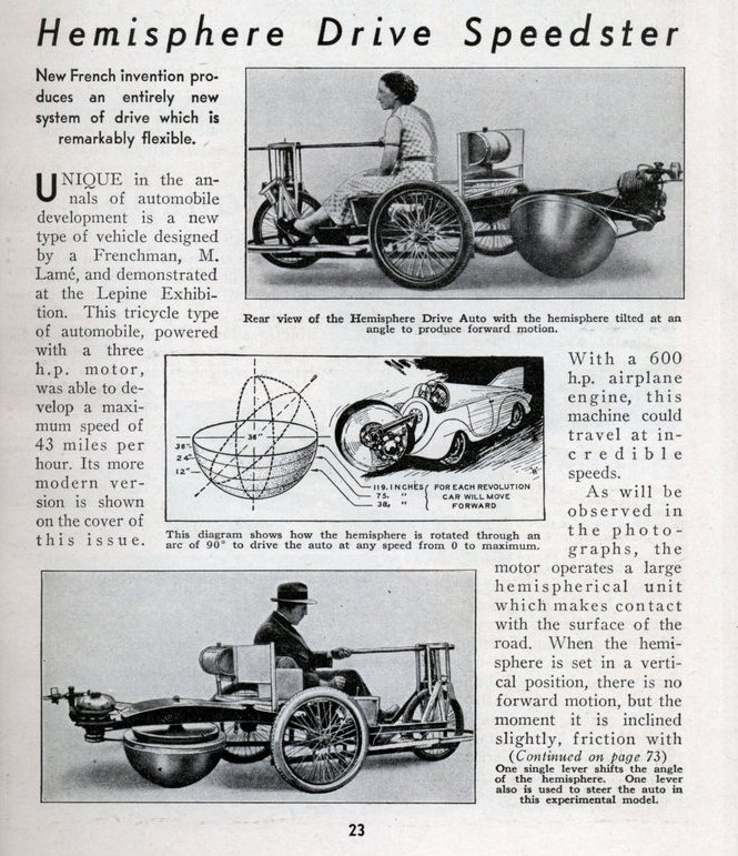
Left: The Hemisphere-Drive tricycle: 1938

The article from Mechanics & Handicraft says it all. The transmission is combined with a fourth wheel in the shape of a half-sphere, so tilting it gives different effective wheel-sizes and thus a different effective gear ratio, giving a infinitely variable drive and eliminating the gearbox. The article does not confirm it, but presumably you could go backwards by tilting the hemisphere in the opposite direction. The engine is cantilevered out the back of the vehicle. The text says that the hemisphere is tilted to move the vehicle, but there's nothing about lifting or lowering it, so when it was vertical the bottom of the hemisphere would be boring a hole in the road. (The hemisphere presumably had some up-and-down movement to allow for road irregularities) A clutch would of course solve this problem, but if there was one it must have been built into the engine casing.

It would appear that this could only work on a flat surface with the right frictional characteristics. One feels for the no-doubt long-suffering Mme Lame in the top picture.

The middle picture shows a speculative vehicle with some sort of propulsor mounted on a shaft sticking out the front. "With a 600 hp airplane engine this machine could travel at incredible speeds." So could almost anything, but not this...

The Lepine Exhibition mentioned in the text was a competition for inventors. It still appears to be going on today'

This 'Propulseur Automobile' was the subject of French Patent 899,395. (29 May 1945) Quite quick work since Paris had only been liberated from the Germans in August 1944. However research by the Museum Staff has shown that Lame took out an earler French patent 801,207 on 30th April 1935, and a German patent 639,476 on 15th February 1936. It appears that these patents may have described a vehicle with one propelling hemisphere in front and two ordinary wheels at rear, like the magazine cover.

Source: Mechanics & Handicraft Vol 5, No 9, Oct 1938

This is the rest of the text missing from the article above:

...When the hemisphere is set in a vertical position, there is no forward motion, but the moment it is inclined slightly, friction with the road drives the automobile forward and although the speed of the motor is maintained constantly, acceleration and deceleration depends entirely upon the peripheral surface which the hemisphere presents to the road. Thus, knowing the speed of the motor, only a simple calculation is required to determine the speed at which the automobile could be driven. Two factors of importance, not outlined by the inventor, but which must be considered, are the gyroscopic effect of the motor and bumps in the road.

Clearly the article-writer wasn't buying it. 'The gyroscopic effect' might indeed be interesting on cornering. And you would need a very flat road.

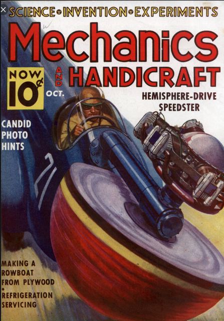
Left: Speculative Hemisphere-Drive car: 1938

This is the cover of Mechanics & Handicraft for that date. The artist has let fairly himself go, and such a spectacular cover no doubt helped the magazine to sell. Here the hemisphere is driven by a radial engine standing up in the air on a stalk; it might be the threatened 600 hp airplane engine, but it doesn't look big enough to produce so much power. The hemisphere is much bigger, this time gives front-'wheel' drive and together with the engine is mounted on a shaft that looks uncompfortably like a forward-firing gun. Well, it was 1938.

This proposal positively bristles with snags. Forward vision won't be great with a big radial engine waving about in front of you. I think the gyroscopic effect would have been formidable, especially at 600 hp speeds. And just how do you steer the thing? With wheels at the back? Two wheels at the back seem to have been envisioned in Lame's earlier patents. (see below)

The middle picture in the article seems to have been derived from this image.

Source: Mechanics & Handicraft Vol 5, No 9, Oct 1938

Left: The Hemisphere-Drive patent: 1938

Fig 1 is the top view. Fig 2 is a side view.

This image is from M Maurice-Luc-Valere Lame's patent and shows very little more than the article. There is an arm carrying the hemisphere, which can apparently be rotated by a string on a pulley; (Fig 2) that would give turning in one direction, but what about the other? Possibly it is working against spring 7.

The patent states that the spring 7 is adjustable to give suitable ground traction with the hemisphere.

Left: The Hemisphere-Drive patent: 1938

The patent text specifies that the 'hemisphere' is inflatable like a tyre, and not truly hemispherical. It is a solid of revolution of which BC is circular, and AB follows the formulae of Muesnier. The next bit of the patent is rather obscure but seems to indicate that this combined shape was to maintain the reinforcing wires of the 'hemisphere' always in tension. D appears to be a metallic cap on which the 'hemisphere' rested when it was not tilted to give propulsion.

Here is an account of Meusnier's theorem. This theorem in differential geometry was proved by Jean Baptiste Meusnier in 1779.

This is the simplest statement of the theorem I have found:

"The curvature of a surface curve equals the curvature of the normal section through the tangent to the curve divided by the cosine of the angle between the plane of this normal section and the osculating plane of the curve."

Whether that has a valid application to reinforcing wires in this case I do not know. The 'formulae of Muesnier' do not get much traction with Google; but this may be reference to Muesnier's discovery of nontrivial minimal-surface examples; the catenoid and helicoid. Neither seem relevant here.


HEMISPHERE-DRIVE TODAY

From the negative comments above you might assume that the hemisphere drive vanished without trace in 1945. That was certainly my expectation when this museim gallery was opened. But you would be wrong...

Hemisphere drive is now described as the application of a Hemispherical Omnidirectional Gimbaled wheel, or HOG wheel. There is a Wikipedia page. It is considered useful in some robots as the propelling force can be quickly vectored in any direction by tilting the hemisphere side-to-side and/or front-to-back, and also gives an infinitely variable drive.

Left: The Next Wheel car: Tokyo 1988

Once again all the information available on the Next Wheel at present is in the article. It seems odd that the hemispheres visible seem to be of different sizes. 'No clumsy steering wheel'? What's wrong with a steering wheel?

This could be handy for sideways parking, but not handy enough to make up for all the other problems. For less radical approaches to sideways parking, see the 5-wheeled cars on the N-wheeled car page.

There was also a report of this event in the San Francisco Examiner for 24 December 1988, but it is behind a paywall. No other information has so far been found.

Source: New Scientist" for 10 Dec 1988

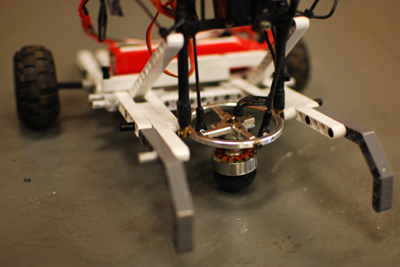
Left: HOG Drive for a robot: USA 2011

HOG = Hemispherical Omnidirectional Gimbaled wheel

This was built by Curtis Boirum, a grad student at Bradley University, in Peoria, Ill. It featured at the 2011 RoboGames symposium. It was apparently invented (or re-invented) frm scratch and was not based on the Mechanics & Handicraft article.

This drive is nowadays being called a "Singularity Drive System," referring to the zero-gear-ratio point with the axle vertical, which is a mathematical singularity. This is to be deprecated as it sounds like it involves using black holes to travel faster than light. Or something like that.

You can see more on robotic applications here at IEEE. There is a video of the device scooting about in all directions.


HEMISPHERE-DRIVE EFFICIENCY

It seems to me that as a means of propulsion it must be inherently inefficent. The hemispherical rubber tyre of Monsieur Lame will not contact the road at a point, but over an area called the contact patch, as the tyre deforms under load. Therefore there are effectively an infinite number of slightly different effective gear ratios in use, and the tyre must be slipping over all but one point of the contact patch. The friction will absorb energy, and wear the tyre out rapidly.

I would be interested to hear other people's thoughts on this.

Back to Home PageBack to The Museum EntranceTop of this page