Many, many, variations on the standard IC engine have been proposed, varying from the thoroughly plausible to the frankly ridiculous. However three-cycle engines are very rare. Two-stroke and four-stroke engines are common. (the latter much more so) Engines exist or have been proposed with 5 strokes and with 6 strokes but three-stroke engines are truly a tiny minority, and it is not clear if a single one was ever built.

THE KORWIN & REBIKOFF THREE-CYCLE ENGINE
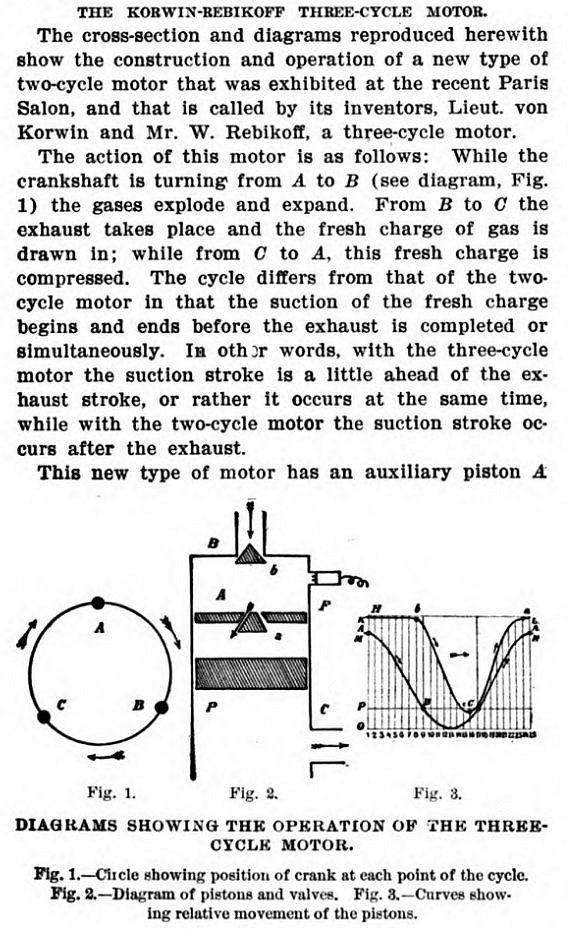 |
| Left: The Korwin & Rebikoff Three-Cycle Engine: Apr 1909
This engine was designed to power aeroplanes. Aero-engine design was in its infancy at the time, and there was much debate as to whether two-stroke or four-stroke engines were best. A two-stroke engine would (in theory) give twice the amount of power for the same weight, but in practice there were difficult problems to overcome.
Korwin & Rebikoff seem to have decided that a three-stroke engine would be a good compromise between two and four strokes. The upper auxiliary piston drew in a fresh charge through the automatic inlet valve B at the top of the cylinder, and at the appropriate point in the cycle transferred it to beneath the main (lower) piston. This allowed great overlap of induction and exhaust processes without the partial mixing of charge and exhaust that occurs in two-stroke engines.
The valve in the upper piston was exposed to the full heat and force of combustion, but this is no worse than the situation of an exhaust valve in a four-stroke engine; in fact rather better as hot exhaust gases did not flow over the upper side of the valve.
No picture of an actual engine has been found so far; it is entirely possible none was ever built.
Source: Scientific American. Vol 67, Jan-Jun 1909. Sci Am Supplement 1730, Foreign Aeronautic Motors-III Feb 27 1909 p133
|
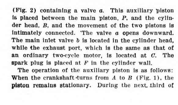 |
| Left: The Korwin & Rebikoff Three-Cycle Engine: Apr 1909
More detail on the three-stroke cycle.
Source: Scientific American. Vol 67, Jan-Jun 1909. Sci Am Supplement 1730, Foreign Aeronautic Motors-III Feb 27 1909 p133
|
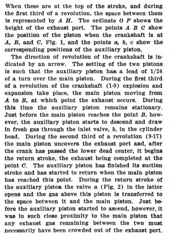 |
| Left: The Korwin & Rebikoff Three-Cycle Engine: Apr 1909
More detail on the three-stroke cycle.
Source: Scientific American. Vol 67, Jan-Jun 1909. Sci Am Supplement 1730, Foreign Aeronautic Motors-III Feb 27 1909 p133
|
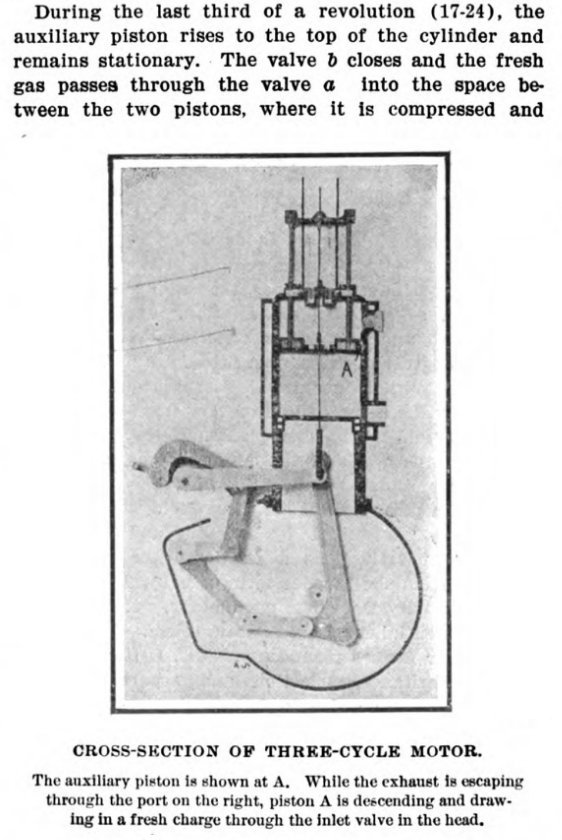 |
| Left: The Korwin & Rebikoff Three-Cycle Engine: Apr 1909
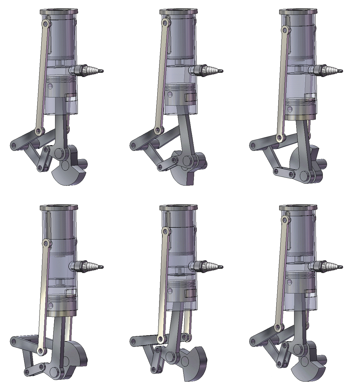
A two-D model of the engine, showing one of its drawbacks; a complicated system of levers to move the pistons in the right phase. Leaving aside the complexity, the levers double the width of the bottom half of the engine, and this is not helpful as an aeroengine needs to have the smallest frontal area possible to reduce aerodynamic drag.
Source: Scientific American. Vol 67, Jan-Jun 1909. Sci Am Supplement 1730, Foreign Aeronautic Motors-III Feb 27 1909 p133
|
 |
| Left: The Korwin & Rebikoff Three-Cycle Engine: Apr 1909
Animation showing the movement of the two pistons and the operation of the levers.
Another brilliant animation by Bill Todd.
|
 |
| Left: The Korwin & Rebikoff Three-Cycle Engine: Apr 1909
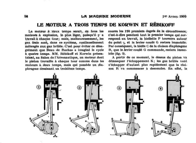
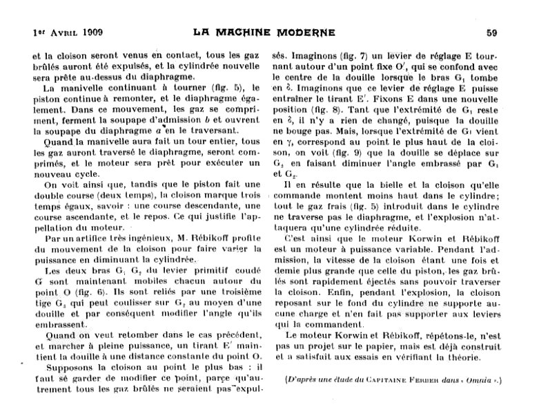
This is the only other article found on the engine so far.
You can find the original article here.
Source: La Machine Moderne, 1 April 1909, p58
|
 |
| Left: The Korwin & Rebikoff Three-Cycle Engine: 1909
Source: La Machine Moderne, 1 April 1909, p58
|
 |
| Left: The Korwin & Rebikoff Three-Cycle Engine: 1919
Source: La Machine Moderne, 1 April 1909, p59
|

JOSEF VON KORWIN (1870? -1920)
Von Korwin was primarily a military balloonist, from Austria. No portrait has so far been found.
He was an officer in the Austrian Army, becoming Commander of the Military Ballooning Department in 1903.
He made 3000 ascents (150 of them were considered "voyages"), including an 'Epic flight' in summer 1903 covering a distance of 700 Km,
and an 'Epic flight' in June 1904, when he landed between two buildings in Vienna and had to be rescued. See NYHerald for 13 June 1904.
In May 1906 he crossed the English Channel, with someone called Prince Jaime. You can read about it here . (in German)
On 3 June 1906 he attempted a Trans-Baltic flight, but was blown out over the Atlantic Ocean, eventually landing safely in France.
There is some more info on him here. He designed a monoplane in 1911, no doubt the new engine was supposed to power it.
No trace of Rebikoff has so far been found.

OTHER THREE-CYCLE ENGINES
 |
| Left: The Williams Three-Cycle Engine: 1985
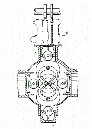
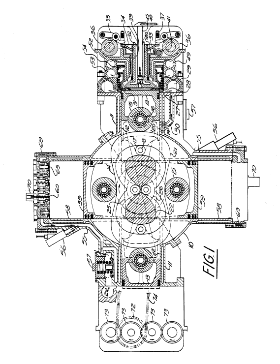
The Williams patent describes a cam engine, the two lobes on the cam allowing three (or indeed four) phases of an IC cycle to be completed in one revolution of the output shaft. There were four cylinders arranged radially around the shaft, making for a less than compact layout. The heart of the idea is to compress the mixture in one cylinder then inject it into a separate variable-volume power cylinder "Without any appreciable change in pressure". Oh really? The variable-volume of the power cylinder is used to vary the power output; that hardly seems an improvement on the simple throttle.
The patent claims that: "For the extra weight of compressor cylinders, compressor pistons and drive rollers, compressor valve gear and high pressure charge distribution ducts, the effective power output of the engine is doubled, as compared with a four cycle version, without increasing the weight of the basic engine, since the piston delivers power during every downstroke." Hmmm.
The engine is unknown to Google (apart from the patent) and it seems unlikely that any prototype was built.
Source: US patent 4,493,296: 15 Jan 1985 'THREE-CYCLE ENGINE WITH VARYING COMBUSTION CHAMBER VOLUME'. The patent is 29 pages long and includes 22 diagrams.
References cited by Williams:
US patent 947,226 Dorfell, Jan 1910
US patent 1,319,756 Chorlton, Oct 1919
US patent 1,443,885 Owen 14 Jan 1923
|
 |
| Left: The Williams Three-Cycle Engine: 1985
This gives a rather better idea of the complexities involved in this engine. The two horizontal cylinders compress the charge while the vertical cylinders create the power. There are relief valves (57, bottom left) to cope with premature explosion of the charge. The mushroom-shaped thing 32 on top of the piston is threaded and is rotated by a worm gear to vary the power cylinder volume.
There is a very complicated valve system for the power cylinder, using two sleeve valves; admission sleeve valve 31 and exhaust sleeve valve 27. The mode of operation is very involved, and I suggest not practical.
Source: US patent 4,493,296: 15 Jan 1985
|
 |
| Left: The Ward Three-Cycle Engine: 1993
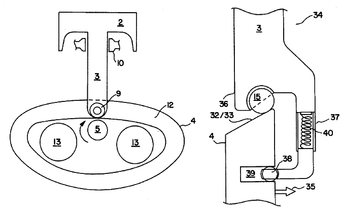
The Ward patent gives only the sketchiest mechanical details. The piston 2 is rigidly attached to a connecting-rod 3, which passes through a seal 10. The roller 9 is held against the large cam by the arrangement on the right. The cam rotates around the main shaft 5. The circles 13 represent cut-outs for reducing the weight of the cam and for balancing.
The patent text appears to have been written by someone with a deep technical knowledge of IC engines, but the design does not look practical; cam engines have never succeeded. The engine is unknown to Google and it is unlikely any prototype was built.
Source: US patent 5,454,352: 3 Dec 1993 'VARIABLE CYCLE THREE-STROKE ENGINE'.
References cited by Ward:
US patent 1,312,585 Shepherd 12 Aug 1919
US patent 4,301,776 Fleming 24 Nov 1981
US patent 4,387,672 Crocker 14 June 1983
|
 |
| Left: The Barberato Three-Cycle Engine: 2012
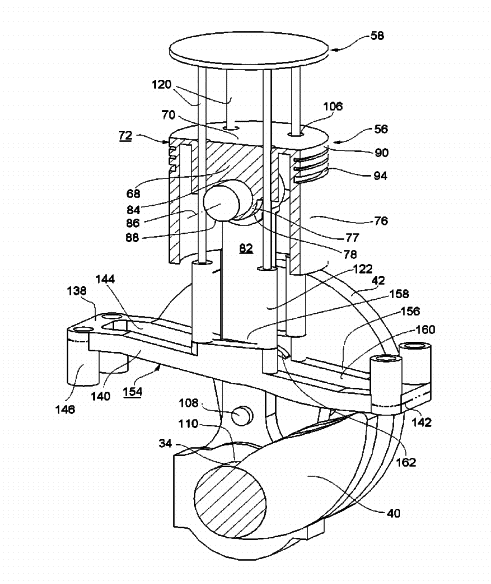
The Barberato engine closely follows the principle of the Korwin & Rebikoff design, and one can't help wondering if there was a bit of copying going on here. However there is here no valve in the upper piston.
Once again there are two pistons moving quasi-independently so the cylinder events can be fitted into three strokes rather than four. This time the upper piston is moved by four vertical rods poking up through the lower piston, moved by a huge cam 40 that is integral with the crankshaft. There are four guides to align the rods.
The practicality of this plan is doubtful. There are four extra holes in the lower piston that will need to be adequately sealed. The enormous cam on the crankshaft seems very likely to cause major balance problems.
No evidence has been found that this engine was ever built.
Source: US patent 8,215,268, 10 July 2012
|


