Updated: 6 Feb 2004


Uniflow Steam Engines. |
Updated: 6 Feb 2004
 
|
Remarkably, there was a Uniflow locomotive running on the South Eastern Railway in Britain long before this. The 2-2-2 "Man of Kent", was converted in 1849 to what was essentially the same Uniflow system as popularised by Stumpf; the designer of this engine is unknown. See Uniflow Steam Locomotives in the Unusual Locomotives wing of the Museum.
Some isolated facts:
The uniflow principle was first used in England by Jacob Perkins in 1827.
A uniflow engine was patented in the USA by Eaton in 1857, and used to power two small steam-boats on Lake Ch-. (full name of lake missing)
Leonard Jennett Todd took out a patent (No. 7801) in 1885. (In the USA?)
Nevertheless, the first commercial manufacture of a stationary Uniflow engine was in 1908. Erste Brunner Maschinenfabrik of Brunn, in Austria, converted an 80 hp single cylinder engine to use a Uniflow cylinder designed by Stumpf. It had Lentz valves.
The success of this engine led to Uniflow manufacture in England, Germany, Denmark, and the USA, and soon there were hundreds in operation.
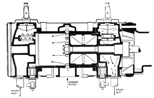
 | Left: The cylinder of a stationary uniflow engine.
|
A conventional double-acting cylinder admits and exhausts steam from each end of the cylinder. This area is therefore cooled by the exhaust steam as it exits, and has to be wastefully heated up again by the hotter incoming steam. The Uniflow system got rid of the exhaust steam by another route: in the middle of the cylinder was a ring of exhaust ports that were uncovered by a long piston at each end of its stroke. This required the cylinder to be twice as long as the piston stroke. Thus steam was admitted at each end but always exited at the centre of the cylinder, allowing a constant temperature gradient to form along each half of the cylinder. This allows greater expansion without condensation in the cylinder, and promises higher thermal efficiency. The expansion ratio could be as high as 35 to 45 if a condenser was used to generate a good vacuum at the exhaust ports.
This attractively simple idea had some practical drawbacks. The large expansion ratio required a large cylinder, and to get a reasonable amount of power out the rotational speed was usually higher than that of ordinary (counter-flow) engine, typically 180 rpm as opposed to 100 rpm. This put serious demands on the admission valves, which in some cases were open for only 50 milliseconds with an early cut-off.
The Uniflow principle appeared to be a beautifully simple way of improving efficiency, but even in stationary use it bristled with practical problems.

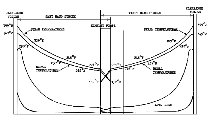
Above: An indicator and cylinder-temperature diagram for a condensing uniflow engine; it must be condensing because cylinder pressure drops below atmospheric when the exhaust ports are uncovered. Note the small differences between the steam and cylinder metal temperatures. Note also that I am assuming you know what an indicator diagram is... Data is from a 1925 paper by Prof Charnock.
The central part of the cylinder was cooler, and expanded less; it was not unknown for a piston to seize solid in the centre of its travel. To allow for this, cylinders had to be bored so they were wider in the middle. Starting a condensing stationary Uniflow engine could be a nerve-racking business; if water was drawn into the engine due to a failure of the condenser extraction pump to get into action quickly, the small clearances at the cylinder ends meant the results were likely to be very destructive.
Because of the high pressure acting at the start of the stroke, the moving parts had to be massive to cope with the forces. A heavy flywheel was needed to even out the large variations in torque as the steam pressure in the cylinder varied over a wide range,
The exhaust ports were of large area, as they surrounded the cylinder in a ring, but were only open for a short period. Some steam remained when they closed; this was compressed as the piston returned towards the inlet end. This was thermodynamically advantageous as it prevented the incoming steam from being cooled, but could give excessive compression under adverse conditions. Some designs had auxiliary exhaust valves next to the inlet valves to cope with this, particularly with long admission timings,and some of the simplicity and efficiency is at once compromised; this was sometimes called a "Semi-Uniflow" type.
Bibliography: Newcomen V43.


