This page began when I stumbled across one of Nikola Tesla's more obscure patents; see below.

THE ACHESON CALELECTRIC GENERATOR
 |
| Left: Diagram from Acheson's patent of 1889
This machine is supposed to generate electricity. It is claimed that starting and stopping the current passing through coils B generates electricity in the circuit D if D is being heated. Heating a magnet to above its Curie point does not appear to be involved.
Mr Acheson says:
"My invention is based, primarily, upon the discovery that if what is known to those skilled in the art as the 'magnetic whirl' is produced
in or about an electric conductor which is traversed by currents of heat an electric current will be generated in said conductor at each establishment and disestablishment of such magnetic whirl cutting said conductor. I have also discovered that such electric currents may be produced in such a conductor in a manner so that they may be utilized as power for all purposes for which electricity is applicable."
The 'magnetic whirl' is a phenomenon unknown to Google; 'those skilled in the art' are going to be hard to find. It appears that Mr Acheson was wholly deluded, and the Patent Office not awake enough to detect what appears to be pure nonsense.
Source: US Patent number 375,408 dated 27 Dec 1889
|
THE TESLA THERMO-MAGNETIC MOTOR
Nikola Tesla was a great man, to whom we owe AC electricity distribution and the induction motor, though it is well known that he lost the plot in a major manner towards the end of his life. The Thermo-Magnetic Motor, however, was patented in 1889, not long after his greatest success; the sale of the patent rights to his polyphase system of alternating-current generators, transformers, and motors to George Westinghouse, head of the Westinghouse Electric Company, in May 1885.
The thermomagnetic motor, however, was not exactly a triumph. It exploits the fact that ferromagnetic materials lose their magnetic properties when heated above a critical temperature. This is called the Curie temperature. Iron has a high Curie temperature, around 700 °C, and this complicates the design.
There is a brief article on thermomagnetic motors in Wikipedia.
 |
| Left: Diagram from Tesla's patent of 1889
Assume that we start with the armature A attracted to the magnet N. A is heated by the gas burner H, loses its magnetic properties and is pushed up and away from magnet N and burner H by the spring W. A then cools, becomes magnetic again, and is attracted back to the magnet, where the burner starts to heat it up again. The cycle turns the flywheel 13 through connecting rod 12.
Tesla took out US Patent number 396,121 dated Jan 15, 1889, though why he bothered is hard to fathom. The patent shows several variation on the idea, including the use of an electromagnet instead of a permanent magnet.
Source: US Patent number 396,121 dated Jan 15, 1889
|
The obvious problem is that a mass of iron such as armature A can only be heated and cooled slowly. This engine would be hard pressed to run at 1 rpm, and its power output would be negligible.
 |
| Left: Three variations on Tesla's motor from the patent of 1889
The motor on the left has an electromagnet rather than a permanent magnet. This seems rather perverse as I should think it is guaranteed that the power to energise the magnet would vastly exceed the output of the motor. There is a different spring arrangement and stops to limit over-vigourous oscillation; little chance of that, I feel.
The motor at the centre is a minor variation on the version above.
The motor on the right has an iron piece that moves inside the electromagnet and also moves a cover to stop the armature being heated. This is probably the most impractical of the lot.
Source: US Patent number 396,121 dated Jan 15, 1889
|
 |
| Left: Tesla's Pyromagnetic Electric Generator from the patent of 1890
This design by Tesla is radically different from his previous patent. The magnetic element is now a bundle of close-packed iron tubes, as in the Edison patent #1 below. The tube bundle is continuously heated by the furnace in the middle, but periodically cooled by water intermittently sent through the tubes; this cools the iron below the Curie point, and the changing magnetic field induces currents in the two coils. This is the output of the generator; I should think it would be microscopic, given the inevitably slow rate at which the magnetic field changes. Not one of Tesla's better ideas.
Source: US Patent number 428,057 dated 13 May, 1890
|
EDISON'S PYROMAGNETIC MOTOR: #1
Thomas was also a great man, and he had at least two goes at a thermomagnetic motor.
 |
| Left: Thermomagnetic motor patent awarded to Edison: 1888
Edison here addresses the problem of rapidly heating and cooling a cylindrical armature composed of thin-walled iron tubes in a magnetic field. Two quadrants around the cylinder of tubes are heated by gases rising from the furnace B. The remining two quadrants are cooled by currents of air that are the draught of the furnace, drawn through pipe e; it is hard to accept that this had much cooling effect. The chimneys f and g carry away the furnaces gases from the top of the cylinder of tubes.
The diagram shows the motor driving a dynamo D, via a considerable speed-up gear ratio. This dynamo is providing the current for the large electromagnet that acts on the the cylinder of iron tubes. Just above the dynamo is handle for starting up the system. It is difficult to believe there was any power left over to be utilised externally.
Source: US Patent number 380,100 dated 27 Mar 1888
|
EDISON'S PYROMAGNETIC GENERATOR: #2
 |
| Left: Thermomagnetic generator patent awarded to Edison: 1892
This is Thomas Edison's second attempt; this is billed as a generator of electricity rather than motion, so Edison was perhaps following the same route as Tesla.
This machine again uses bundles of iron tubes as the magnetic element. These are rotated around the central axis so they are alternately heated by the furnace D with the hot gases going up at G, and cooled by the draught of air at F, as in the previous Edison patent. Each of the eight bundles of tubes has a coil wound round it, and the changing magnetic field induces currents in these coils. They are connected together and the electrical output is taken off via slip-rings e,f. There is an electric motor I which keeps the whole carousel turning. The electricity lights lamps at L; I think this is a bit optimistic.
Source: US Patent number 476,983 dated 14 June 1892
|
At this point I concluded that even the greatest of innovators have their off days, and was prepared to write off thermomagnetic engines as one of the deadest dead-ends in the history of power production. However... fortunately I did a quick Google before committing page to web, and I was surprised to find that research into thermomagnetic engines was alive and well.
 |
| Left: John Hazelwood patent: 2012
This is a very long patent of 19 pages with 18 diagrams, but it does not seem to advance the technolgy at all. There is a wheel with ferromagnetic 'wafers' attached to it. These are heated by a gas jet as they pass one of the poles of a permanent magnet. There seem to be no special cooling arrangements for the wafers.
Apart from the patent, Mr Hazlewood and his engine are unknown to Google.
Source: US patent 8,242,662 12 Aug 2012
|
THE AMATEUR SCIENTIST THERMO-MAGNETIC ENGINE
'The Amateur Scientist' was a monthly feature in Scientific American for many years, though it is now long gone. One of the experiments described was a thermomagnetic motor composed of a wheel with a vertical axis, its periphery being studded with lighter flints, and part of it being in the field of a permanent magnet. I now have the details:
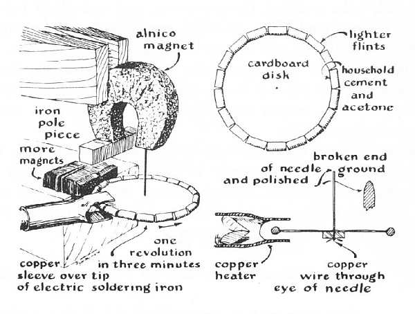 |
| Left: A thermomagnetic motor made with lighter flints
This engine was devised by Roger Hayward. The lighter flints on one side of the permanent magnet (labelled "more magnets" in the illustration) are heated by a modified soldering iron, and so are not attracted to the permanent magnet. The unheated flints on the other side of the permanent magnet are attracted, and so the wheel revolves in the direction shown.
The power output however appears to be tiny, and Hayward apparently had to resort to a kind of magnetic bearing involving a needle to get any movement at all. Even then, the rate of rotation was only once in three minutes; I can only assume that lighter flints are but weakly magnetic and the forces involved are very small. Lighter flints are not made of flint stone at all, but Ferrocerium Apparently the active ingredient in this case is the cerium; cerium alloys are used in permanent magnets.
Source: Scientific American July 1959
|
CONTEMPORARY THERMO-MAGNETIC MOTORS
Researching this topic is rather frustrating because almost all the information is in the form of research papers locked up in websites you have to subscribe to. However I have gleaned some information...
The fact that metallic gadolinium is ferromagnetic with a Curie temperature of only 294 degK (21 degC) has been used to make simple thermomagnetic engines for laboratory demonstrations. These can be driven by an electric lamp or by sunlight. Presumably these engines will not work on a warm day as then the material would always be above the Curie temperature.
There appears to be current interest in thermomagnetic engines that can use the considerable heat in IC engine exhausts to generate power. These use materials with much higher Curie temperatures than gadolinium, such as iron-nickel-chromium alloys. The original material for what follows was written in Japanese; I have done my best with translation but accuracy-wise you'd better keep your fingers crossed.
Modern thermomagnetic engines are not reciprocating like Tesla's proposal, but produce continuous rotation. The ferromagnetic material is a rotor in the form of a ring or cylinder, which moves into a magnetic field created by permanent magnets. It is heated at one point so that it has lost its ferromagnetism when it leaves the field. There is therefore a steady net pull on the rotor, causing it to turn on its axis. The rotor is then cooled and regains its ferromagnetism before it re-enters the magnetic field.
 |
| Left: Configuration of a current experimental thermomagnetic motor.
A practical version of this can generate 100W of power at 1.5 revolutions per second.
|
This appears to be delightfully simple, and so it is; but there are problems. An obvious one is that heating and cooling cannot take place very quickly, so the speed of rotation is very slow, typically 0.5 to 1.5 revs per sec. Presumably this can be geared up to drive an electric generator.
Another difficulty is that eddy currents are induced in any conductor moving in a magnetic field, and this effect acts against the movement of the rotor.
 |
| Left: Power and torque curves for the thermomagnetic motor.
The efficiency is a not especially stunning 0.021%. This is 0.19% of the possible Carnot efficiency.
|
THERMO-MAGNETIC PATENTS
The best-known ones are illustrated above. "Magnetic Motor with Temperature-Related Activation" (US Patent 5,397,948) sounded promising, but it only uses the Curie effect to move latches on cooker doors, etc. There is no continuous generation of power.
<--
| 375,408 1887 Acheson
|
| 380,100 1888 Edison
|
| 396,121 1889 Tesla
|
| 428,057 1890 Tesla
|
| 476,983 1892 Edison
|
| 1,431,545 1922 Schwartz
|
| 2,016,100 1935 Schwartzkopf
|
| 3,445,740 1969 Merkl
|
| 3,743,866 1973 Pirc
|
| 4,447,736 1984 Katayama
|
| 4,730,137 1988 Vollers
|
| 2004 Takizawa et al
|
-->
LINKS
As previously noted, information on thermomagnetic motors on the web is not very accessible. The stuff that is open-access mostly relates to laboratory demonstration models of neglibible power output and utility. To find more of these, put "Curie motor" or "Curie engine" into Google. Here are some results:
www.physics.ucla.edu
jamsci.org
www.feiradeciencias.com Apparently based on the Scientific American motor.
www.imagesco.com (Nitinol engine)


