The surface combustion boiler burns its fuel, which has to be gas or a vapourised liquid, on the surface of a catalyst rather than as a visible flame. The principle was worked out by Professor W A Bone of the Imperial College of Science and Technology at South kensington, London, from 1902 onwards. Imperial College is one of the top universities and Bone was a Fellow of the Royal Society, so we're not talking eccentric lone inventor here. In association with C D McCourt the Bonecourt boiler company was set up.
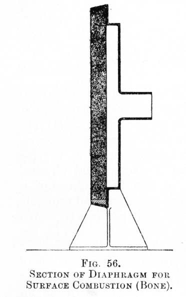 |
| Left: Porous refractory diaphragm for space-heating by surface combustion: 1917
The mixed gas and air flows in from the right, diffuses through the porous diaphragm, and burns without visible flame on its surface, creating such high temperatures that only calcined magnesia or carborundum can be used for the refractory diaphragm.
Image from Chemical Discovery & Invention in the 20th Century by Sir William Tilden FRS, published by George Routledge & sons, 1917
|

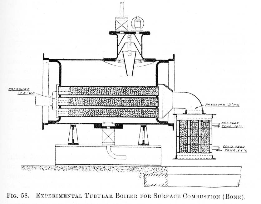 |
| Left: Experimental Bonecourt surface-combustion boiler: 1902-09
The gas and air mixture comes in from the left, burns on the surface of the refractory material in the fire-tubes, and then passes out through the feed-heater on the right. The tubes are 3 feet long and 3 inches diameter, in a cylindrical shell capable of withstanding 200 psi.
The extension on top holds the steam stop valve and a safety valve. The cone-shaped things are presumably for steam/water separation.
Image from Chemical Discovery & Invention in the 20th Century
|
 |
| Above: The Bonecourt surface-combustion boiler: 1902
Image from Chemical Discovery & Invention in the 20th Century
The sucessful results obtained with the experimental boiler led to the erection of one ten times the capacity at the Skinningrove Iron Works in North Yorkshire, fired by waste gases from an Otto by-product coking plant. A photograph of that boiler is shown further down the page.
The boiler was a cylindrical drum 10 feet in diameter and 4 feet from front to back, fitted with 110 steel fire-tubes 3 inches in diameter and packed with granular refractory material. The vertical pipe at the right supplied washed gas from the coke-ovens at a pressure of only 1 or 2 inches of water. From this pipe two control valves fed two distribution chambers on the boiler end. The gas, mixed with a controlled amount of air, was drawn through a short mixing tube into the combustion tubes and burnt without flame as described above. The exhaust gases passed out to the left and were collected in a semi-circular chamber at the rear of the boiler and then passed through a feed-water heater. (Presumably the smaller cylinder immediately to the left of the boiler) The exit from this led to a fan driven by electric motor which drew the gases through the system, their exit temperature being 100 degC.
|
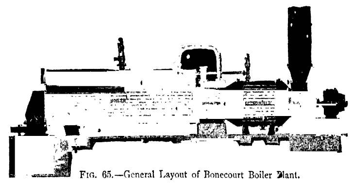 |
| Left: Bonecourt boiler in linear format
The boiler is on the left, and the economiser or feed-heater on the right. At the extreme right is the suction fan and exhaust stack.
Original source unknown. (Downloaded from the West Bengal Public Library Network) Apologies for the dire image quality.
|
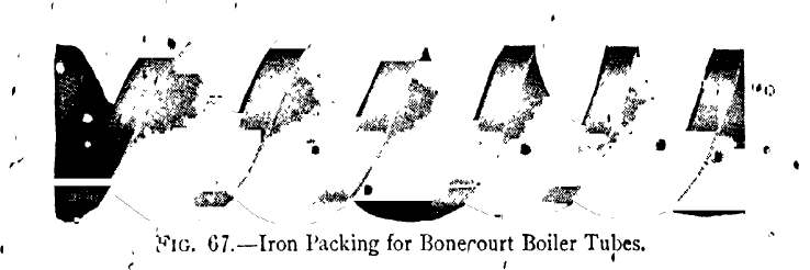 |
| Left: Spiral iron packing to replace refractory material
The refractory material in the firetubes tended to crumble and produce dust. It was replaced by spiraled iron cores which were claimed to act as well the refractory and cause a spiral flow of the combustion gases to enhance heat transfer.
Original source unknown. (Downloaded from the West Bengal Public Library Network) Apologies for the dire image quality.
|
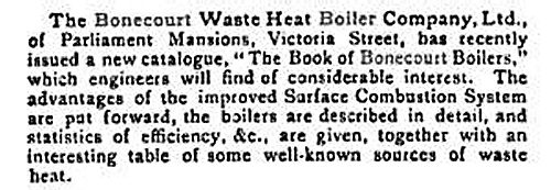 |
| Left: Announcement of "The Book of Bonecourt Boilers"
Now it would be interesting to get hold of a copy of that...
From Chemical News and Journal of Industrial Science, Volume 114, 15 Sept 1916.
|
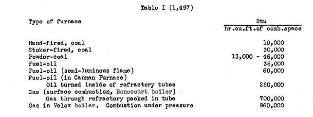
Now the question is, what practical advantages did the Bonecourt surface-combustion boiler have over more conventional equipment? This is rather glossed over in Chemical Discovery & Invention in the 20th Century, but according to Llewellyn Michael Kraus Boelter in "Heat Transfer Notes". (These appear to be lecture notes published by the University of California in 1946) The extract below shows the amount of heat liberated per cubic foot of combustion space. The Bonecourt boiler comes second, not much after the exotic Velox system, in which fuel is burnt under considerable pressure. The third entry (the Cannan furnace) produces about a third of the heat output of the Bonecourt boiler, with hand-fired coal coming nowhere.
"The Steam Boiler Yearbook and Manual IV" (Paul Elek Publishers Ltd, London 1948) says:
"The simplicity of design and operation renders both the vertical and horizontal types of Bonecourt boilers and heaters eminently suitable for all purposes where steam at a constant pressure and water at an even temperature is required, especially as the makers state that no supervision is wanted and no labor entailed other than lighting-up or extinguishing, and maintainance is reduced to a minimum." also "... fired by means of a separate jet into each boiler tube. This provides a large heating surface, giving a high evaporative capacity and quick steaming from cold, for boilers which are very compact in size."
I don't quite understand the staement that "no supervision is wanted" because keeping the water level in a boiler correct is a matter of life and death. Automatic feedwater regulator systems existed, but it would be most unwise to rely on them completely.
THE BONECOURT COMPANY
At some point the Bonecourt company became Spencer-Bonecourt with an address at 32-33 Farringdon Street, London, EC4.
In 1927 they became part of the well-known firm of Babcock and Wilcox. (Grace's Guide)
The manufacture of Bonecourt boilers continued until at least 1948 by Messrs. Town Gas Boilers (Bonecourt) Ltd. of London.