You would think that no-one would make a steam boiler that rotated as it worked. You would be wrong. Against all the evidence, a number of people were able to convince themselves that a rotating steam boiler would be a really good idea.
The original background to this notion was increasing concern in the USA about boiler explosions. These were occurring at twice the rate they did in Europe, and usually caused greater loss of life as differing planning laws meant that in the USA a large steam boiler was more likely to be close to a busy street.
It was believed that one of the major safety problems was stresses set up by unequal thermal expansion. Rotating the boiler continuously as it worked was advocated as the best way to equalise the temperatures of the various parts.
Later developments were concerned with compact steam power-plants for aeroplanes rather than safety.
ASHWELL'S REVOLVING BOILER: 1847
For a long time the Pierce Rotary Boiler shown below was the only occupant of this gallery of the museum. Now, however, a much earlier example of a rotary boiler has been discovered. This boiler was the invention of Thomas Ashwell of Stockbridge, Mass. Mr Pierce's effort now looks a lot less original.
The Ashwell boiler was composed of a series of iron tubes, and was tilted slightly to help the flow of steam.
 |
| Left: The Ashwell Revolving Boiler: 1847
A Brick casing
B Convex end-plate
C Worm-drive
D Boiler tubes
E Tubular pivot
G Water level gauge pipe
I Fire-door
J Feed pipe
K Furnace
M Drive-wheel for worm
Each pivot contained a solid plug which carried the various pipes, and did not rotate with the boiler; these were packed in some way to make them steam-tight. The pivots were about 6in diameter for a 7 foot long boiler, and from the diagram appear to have rested on rollers. On one of the pivots was fixed a gearwheel driven by a worm to rotate the boiler about once a minute.
The water-level was monitored solely by means of two try-cocks; only one pipe is shown in Figure 1.
Figure 2 shows a section through the boiler tubes.
Figure 3 shows the worm drive and rollers.
From the US journal Scientific American for April 3, 1847 (Vol2, Iss 28)
This account was published before Mr Ashwell applied for a patent, which under English law would have made obtaining a patent impossible as the idea had already been disclosed.
|
THE PIERCE CENTENNIAL ROTARY BOILER: 1876
 |
| Left: The Pierce Centennial Rotary Boiler: 1876
A is the cylindrical boiler shell, containing longitudinal fire-tubes PP.
The boiler was connected to exit pipe L and the rest of the system via rotating joints with packing boxes I; these were under full steam pressure and would have required some careful design. The boiler was supported on trunnions J, and rotated by the auxiliary steam engine D, through gearing V.
This auxiliary engine appears to work the feed-pump as well. Since it must work continuously to rotate the boiler, the feed-pump was presumably disabled when not required by an unloading valve.
From the US journal The Manufacturer and Builder for July 1876, p150.
|
The boiler has an automatic water-level regulator, which was claimed to work thus: if neither of the lower ends of the tubes M M are below the water surface, the water in globe G will drain away, causing it to rise as it is no longer heavier than the adjacent counterpoise. This motion is communicated to the feed valves via regulating rod U.
Rotary boilers do not appear to have been popular, and so were presumably not a great aid to safety; with extra moving parts under full steam pressure they were probably more prone to failure rather than less. They surely must have been significantly more expensive, and of course the steam consumed to rotate them was not free.
The later rotary boilers described below did not have safety as their prime raison d'etre.
THE HUETTNER ROTATING AEROPLANE BOILER: 1934
Remarkably, I have unearthed another of these things, though I suspect that it went round rather faster than the cumbersome item above. The boiler was intended for a steam-powered aeroplane- a minority interest indeed. The boiler was toroidal in form, and closely integrated with a steam-turbine.
The aim of the inventor was apparently a high power-to-weight ratio, rather than enhanced safety. Steam-powered aeroplanes now have their own page here, where you can read more about the Huettner Steam Plane.
|
Above: The Huettner Rotary Boiler and steam turbine: 1934. The things like dog-teeth are labyrinth seals between rotor and stator.
From the 1960 reprint of the 2nd Edition of The Theory and Practice of Heat Engines by D A Wrangham, pub Cambridge University Press.
Info kindly supplied by David Bowie.
|
The following information comes from Wrangham:
"Huettner Rotary Power Unit
This prime mover is of great interest because it represents a self-contained and completely automatic unit.
"The boiler (1) consists of finned U-tubes, and is integral with the turbine and condenser casing, which is geared to the turbine spindle so that the two revolve in opposite directions at different speeds.
By this gearing a high relative velocity is produced for a moderate rotational speed and turbine diameter. The boiler speed is fixed by the desired working pressure, and having decided on this the turbine spindle must be arranged to run at a speed which will give the best velocity ratio.
Since the steam is unsuperheated, precautions have to be taken against blade erosion by providing drainage belts at each stage. These belts communicate with the water leg of the boiler, and are virtually bleeding points; so that the actual efficiency of the machine should approach that of the Carnot cycle.
To condense the steam and remove any air in solution cooling water is introduced into the casing through pipe (2).
Rotation of the casing flings the water through a nozzle ring into the steam space of the turbine, where rapid condensation takes place in chamber (3).
After crossing this chamber the water and entrained air pass through divergent nozzles which raise its pressure to atmospheric. The surplus water collects in an annular ring (5) until it overflows a rim into a stationary catch ring which runs it to waste."
This explanation raises a lot more questions than it answers. Here are some of mine:
- I assume the turbine would be rotating much faster than the boiler- the boiler and its water will be heavy and mechanical stresses will limit the possible speed. However, the diagram shows the boiler going round faster than the turbine; if the gear dimensions can be relied on the ratio is :1 . And further, the boiler and turbine are going round in the same direction whereas surely they should be going round in opposite directions to maximise the speed difference between them.
- How do you start it? The water won't stay in the boiler unless the machinery is already rotating at a good speed. A source of auxiliary rotational power will be needed until you get steam up.
- I am far from sure that the 'virtual bleeding points' would work as a sort of regenerative feed-heating, which is presumably what Wrangham is getting at; when turbines are bled for this purpose, steam is extracted, not water.
- I am also unclear as to why 'rapid condensation' would take place in such a small space unprovided with cooling fins. And where does the cooling water come from? The steam would have to be completely condensed to get a usable flight time, but Wrangham talks about water running to waste.
- How are you going to stop the water freezing when you aeroplane is parked? You can't add ethylene glycol. Continous heating would be required. I suppose this applies to any steam vehicle.
- The boiler burners are not shown (and the fins on the boiler don't look too convincing- surely they should run fore-and-aft) but they would have to fed air with a fan when starting up.
- I have doubts about the turbine effciency at anything below design speed, but no hard information at present. Turbine nozzle control is going to be hard since the nozzle assembly is rotating with the boiler.
- I really don't see how the entrained air is supposed to be pumped out. And surely, if there is any condenser vacuum, air would be rushing in at (2)?
I have so far found no evidence that the Huettner steam plane ever flew, and I am far from convinced that this engine could work.
Wrangham also makes some general remarks on rotary boilers:
"In the revolving boiler, both the gases produced by combustion and the heating surface move. In fact the boiler, condenser, and power component form one highly compact rotating power unit which is well suited for the propulsion of aircraft. The figure below illustrates the principle on which the boiler is constructed:
|
Above: Rotary Boiler and steam turbine from Wrangham.
From the 1960 reprint of the 2nd Edition of The Theory and Practice of Heat Engines by D A Wrangham, pub Cambridge University Press.
|
"A large number of U-tubes are welded to a hollow spindle, which is rotated in the combustion chamber.
The effects of this rotation are:
- To produce a rapid rate of heat transmission.
- To dispense with the feed pump and feed regulator, the water being flung into the U-tubes by centrifugal force.
- To prevent priming by applying a centrifugal force to the separation surface of the water and steam many times in excess of the gravitational pull.
"The main difficulties which arise with this type of boiler are:
- The difficulty of maintaining mechanical balance in view of the creep of the tubes.
- Erosion of the tubes.
- The inability to vary both power output and speed independently.
If the trouble from mechanical balance could be overcome, this generator would be suitable for purposes where light weight and compactness are of prime importance, but close speed regulation is not required."
The rotating boiler and steam turbine combination below is similar to the Huettner arrangement.
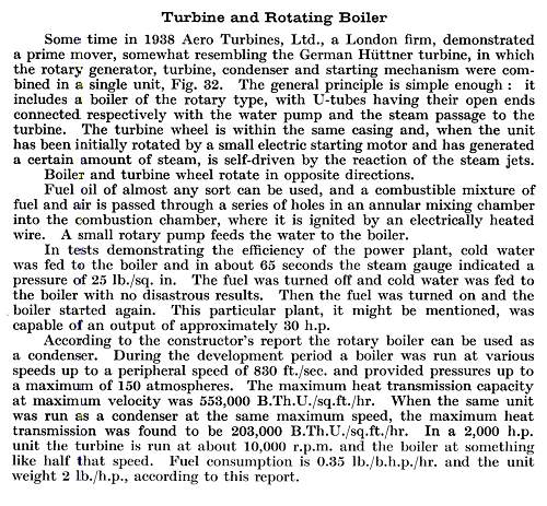
THE AERO TURBINES LTD ROTATING BOILER: 1938
 |
| Left: The Aero Turbines Ltd Rotary Boiler: 1938
This remarkable picture shows a relatively modern rotating boiler, combined with a steam turbine. An annular burner structure heats a series of rotating finned U-tubes, and the steam from them passes directly to a turbine. Note that the exhaust steam goes to an external condenser, unlike the Huettner integrated arrangement. Efficient condensation would be essential for practical use; partly to increase turbine efficiency, but most importantly, to conserve water and give a usable flying range.
From "Gas Turbines & Jet Propulsion" 1944 1st edition by Geoffrey Taylor.
Kindly provided by Alan Lea.
|
 |
| Left: The Aero Turbines Ltd Rotary Boiler: 1938
The text describing the power unit. Note that the report was written by the manufacturers, not an independent authority.
I must admit to having lots of doubts about this intriguing device.
Firstly, the boiler tubes look incredibly short for turning water into steam. There is of course no scale on the drawing (and hopefully no scale in the tubes, because it looks extremely diffcult to remove) but for a normal sized engine their total length could hardly be more than 12 inches.
I have found no trace of Aero Turbines Ltd via Google.
From "Gas Turbines & Jet Propulsion" 1944 1st edition by Geoffrey Taylor.
Kindly provided by Alan Lea.
|
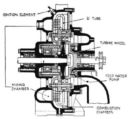 |
| Left: A section through the Aero Turbines Ltd Rotary Boiler: 1938
This drawing is taken from an article on steam aeroplanes in "Flight" magazine in July 1942. No doubt the editor felt that this topic could be safely explored without giving any help to the Germans. Performance data and so on for this engine were given , but they were simply a cut-and-paste of the report quoted above.
It is not at all clear how the feed pump is supposed to work.
From "Flight" 30th July 1942.
|
A ROTARY COMBUSTION CHAMBER BOILER
This boiler does not rotate in its entirety but it does have a rotary combustion chamber:
www.westernwoodfuels.com
A WORD ON BOILER SAFETY
The greatest and most pressing dangers of a steam boiler do not include differential expansion. In order of peril, they are:
- Internal corrosion of the boiler plates until their strength is inadequate. This is particularily insidious, as there are usually no external indications. The only precaution is regular boiler inspections, requiring everything to be cooled down and the manholes opened. If this is neglected...
- Too a low water level so the firebox or whatever overheats and loses strength. This happened in many instances on steam locomotives, which in Europe at least were rarely if ever fitted with low-water alarms. Automatic level regulators were, I think, hardly ever used outside the USA. Fusible plugs appear to have been a long way from foolproof. The vigilance of driver and fireman was usually the only safeguard.
- Excessive steam pressure. Perhaps surprisingly, this is the least danger. Boilers were always fitted with automatic safety-valves, often duplicated, and this precaution only failed on rare occasions where the safety-valves were tampered with, improperly assembled or had been allowed to corrode until they were inoperable.
You might think it would require a rather special incompetence to design a safety-valve that could be assembled in such a way that it did not work; however it happened at least once in Britain. 0-6-2 tank engine No 97 of the Rhymney Railway exploded at Cardiff shed in 1907 because the Ramsbottom safety valves had been wrongly assembled and could not open. Three men were killed.

Bibliography On Boiler Safety:
"Red For Danger" L T C Rolt
"Locomotive Boiler Explosions" C H Hewison


