Gallery opened March 2004
Updated: 29 Apr 2024
More on mechanical rectification patents added here
 
| |
Before the invention of semiconductors, rectification at high currents involved serious losses.
There were various vacuum/gas devices, such as the mercury-arc rectifiers, thyratrons, ignitrons, and Vacuum diodes. Solid-state technology was in its infancy, represented by selenium and copper oxide rectifiers. All of these gave excessive forward voltage-drop at high currents.
One answer was mechanically opening and closing contacts, if you could do it fast and cleanly enough. The wonderful machine shown below was designed by Read and Gimson et al, at BTH Rugby in the early 1950s. It is a three-phase mechanical rectifier working at 220V and 15,000 Amps, and its application was the powering of huge banks of electrolysis cells.
The central shaft was rotated by synchronous motor, driving an eccentric with a throw of about 2mm. (0.077 inch) Push-rods from this operated the contacts. The timing was critical, and was adjusted by rotating the position of the eccentric on its shaft, and by sliding wedges between the eccentric and push-rods.
Crucial to this system were the commutating reactors, inductors that ensured the contacts closed when the voltage across them was small, and opened when the current was small. Without these, contact wear would have intolerably heavy.
This machinery was undoubtedly successful; its efficiency was determined to be 97.25%. Contact life was never fully determined but considerably exceeded 2000 hours. However, the rapid development of the silicon diode made it ultimately a technological dead-end.
Mechanical Rectifiers have a Wikipedia page, but it seems to be based on this Gallery.
THE BATTEN RECTIFIER
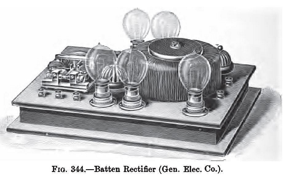 |
| Left: The Batten rectifier system: 1902
The Batten rectifier was essentially a high-speed polarised relay that converted AC into pulses of DC. The well-known author Rankin Kennedy praises it highly in his 1915 book, and describes an early kind of phase-control that reduced the effective output voltage without dissipating power in resistances. He also says it was "the outcome of much experiment", and I'm not surprised. What is a bit surprising is that it worked at all. Kennedy says it is capable of "...working well on circuits of all frequencies." which I beg leave to doubt; we're talking about mechanical contacts moving here.
In this illustration the polarised relay is at the left, and there is a very modern-looking toroidal transformer on the right. The light bulbs are for demonstration purposes.
The The Electrical Review said the Batten rectifier had the following uses: "For instance, it may be employed for charging small accumulators, exciting spark coils, driving small
motors, performing electrolytic work on a limited scale, and so forth."
Sources: The Electrical Review, Volume 50, 3 Jan 1902
The Book of Electrical Installations, p167, by Rankin Kennedy, Caxton Publishing 1915
|
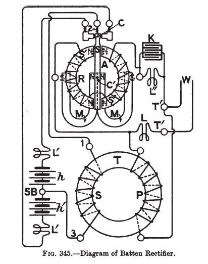 |
| Left: The circuitry of the Batten rectifier system: 1902
Here is the circuitry of the Batten rectifier system. AC power comes in at W and energises the transformer T primary and the windings on the magnet A. The soft iron core S carrying the moving contact is polarised by the permanent magnets M so that it connects the transformer secondary with one of two fixed contacts, depending on the phase of the applied AC. Each fixed contact is connected to the two storage batteries h and h'.
L,L' and L'' represents the light bulbs, presumably inserted for demonstration purposes. K is a capacitor connected across one of the light bulbs; its intended function is unknown.
The principle here is synchronous rectification, which is a form of active rectification. The incoming AC itself switches the current to the appropriate destination, rather than using the one-way properties of diodes or solid-state rectifiers.
The immediate question is just how long are the contacts going to last if they are being hammered at 50 or 60 Hz. The answer seems to be longer than you might think. The Batten principle was used to create high voltages for valve anode supplies up until the 1950s, when all that was available was low-voltage DC, often from a car battery.
Source: The Electrical Review, Volume 50, 3 Jan 1902
|
The Batten principle was developed into the Synchronous Vibrator.
In more innocent times, the word "vibrator" meant only one thing to the radio engineer. It was a way of powering valve car-radios from a car battery.
The simplest version was the asynchronous vibrator which worked rather like an electric bell, that chopped up the 12V DC so it could be applied to a transformer and stepped up and rectified conventionally to a suitable HT voltage. More sophisticated types, known as synchronous vibrators, had an extra pair of contacts that rectified the power, as in the Batten rectifier; this gave lower losses. Vibrators were normally packaged in tin cans that plugged into something like a valve socket for easy replacement, which suggests contact life was indeed an issue. Another disadvantage of vibrators was the emission of acoustic noise.
Vibrators have a Wikipedia page,
There is more info here.
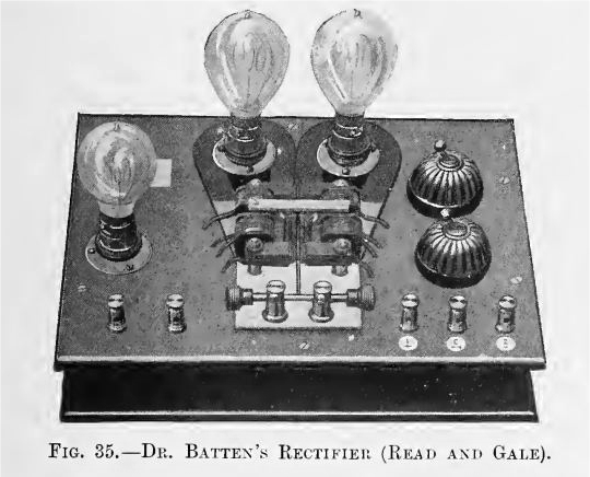 |
| Left: The Batten rectifier system: 1902
Here is another version of the Batten rectifier, the transformer (if there is one) presumably being inside the cabinet,
Batten has so far been elusive, but the knowledge gained here that he was a doctor may help in tracking him down. Given the date, I think we can assume a him. Some possibilities:
Frederick Batten (1865-1918), called the father of paediatric neurology. Gave his name to Batten's Disease, which you don't want to get.
There is a Frank Batten College of Engineering & Technology at Old Dominion University in the USA.
George B Batten MD was a radiologist (ie concerned with X-rays) in Southwark Military Hospital in 1916... and nailed it!
He wrote a paper called "Some Methods of Using the Alternating Current Mains for Rontgen-Ray Work" in the Journal of the Rontgen Society, for July 1910, pages 61-104. I can only see the first two paragraphs of the paper, the rest being behind $42 worth of paywall. Anybody feeling rich? If so go to the Rontgen Society website, where you can pay to download the PDF.
From what I can see there is no doubt George B Batten is our man. He was moved to develop means of rectification when his house was connected to AC mains in 1898, he had then been involved in X-rays for a year.
He was still around in 1930, writing Radiograms of a Fractured Leg Twenty-four-and-a-half Years After Being Wired by George B Batten, MD, DMRE. No picture of him has been found so far.
Source: The Röntgen Rays in Medical Work p61, by Walsh and Jones, 4th edition pub Wiliam Wood 1907
|
 |
| Left: The Batten rectifier system: 1902
This comes from the start of the paper mentioned above.
Here we learn that Batten was aided by George Sutton in the development and that a patent was obtained. Others in the field were Dr Reginald Morton with his rotary rectifier, which I can tell you now has opened up a whole new area of mechanical rectifier enquiry, and Mr Wright with his Dipper, which has so far led nowhere.
Hopefully, one day you will meet Mr Wright.
The final sentence about dental engines is so far wholly mysterious.
Source: "Some Methods of Using the Alternating Current Mains for Rontgen-Ray Work" Journal of the Rontgen Society, for July 1910, pages 61-104.
|

THE MORTON ROTARY RECTIFIER
 |
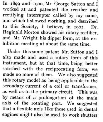
| Left: The Morton Rotary Rectifier: 1907
The Morton Rotary Rectifier used a synchronous electric motor (to the left) to drive a rotating commutator that switched the current so as to achieve rectification. This sounds like a much more promising technology than contacts hammering each other- you just have smooth rotation. But as noted above, the latter worked.
From The Röntgen Rays in Medical Work;
"The rectifier of Dr. Reginald Morton is a beautifully-made machine of this type, with a self-starting mechanism for bringing the motor into
synchronism. It has a massive commutator, and is able to rectify currents of large magnitude in a very perfect manner. It is made by Messrs. Newton..."
The purpose of the two short black handles is obscure; for adjusting contact pressure?
Newton and Co became Newton and Wright Ltd; I think we are on the trail of Mr Wright.
Source: The Röntgen Rays in Medical Work p63, by Walsh and Jones, 4th edition pub Wiliam Wood 1907
|
You can read the obituary of Dr Morton (1867–1944) here, in the Journal of the Radiological Society of North America, republished from the Lancet. It ends with this sobering statement: "...he was one of the few X-ray pioneers who suffered only minor damage from the rays."
THE WRIGHT RECTIFYING INTERRUPTER
 |
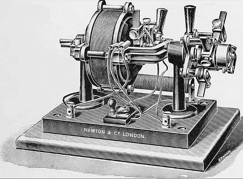
| Left: The Wright Rectifying Interrupter: 1907
The Wright rectifier was another synchronous rectification scheme, using metal bars thrust into mercury cups by cranks on the shaft of a synchronous motor.
From The Röntgen Rays in Medical Work;
"...the same firm also makes a rectifying interrupter of a different kind, which consists of a small motor fitted with one or two cranks on the axle. These carry plungers making contact with mercury cups, as in the 'dipper' break, and the instrument can be adjusted to work either as a rectifier or as an
interrupter for working large coils. It starts easily into synchronous movement with a touch from the finger."
An "interrupter for working large coils" refers to induction coils that have the primary current interrupted periodically togenerate high voltages in the secondary winding. The interrupter was sometimes a contact at the end of the coil, operated by the magnetic field in the core, but externally-driven interrupters based on mercury or electrolytric methods (foremost the Wehnelt interrupter) were also used. The interruptor was sometimes called The Break, the capital letters indicating its importance.
Source: The Röntgen Rays in Medical Work p64, by Walsh and Jones, 4th edition pub Wiliam Wood 1907
|
This sounds like rather hazardous machine. I would have though the interrupting of the current would give rise to sparking and the generation of mercury vapour. You don't want to breathe mercury vapour. Wikipedia should convince you.
The purpose of the twin rheostat on the front is currently unknown.
THE SIEMENS MECHANICAL RECTIFIER
 |
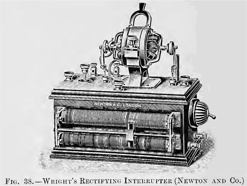
| Left: The Siemens Mechanical Rectifier: 1907
From The Röntgen Rays in Medical Work, referring initially to the Batten rectifier:
"An apparatus of the same (Batten) type, on a larger scale, is made by Messrs. Siemens Brothers, and can be used for charging accumulators, or as a synchronous interrupter for driving large induction coils. In the latter case the contacts and interruptions are arranged to take place near the maxima of the alternating current waves, and the contact surfaces of platinum are massive, to carry large currents and to withstand the sparking. In this form the instrument serves at once as rectifier and as interrupter, and makes the operation of coils from the alternate current mains a simple matter."
It goes on to say: "...the rectifying interrupter of M P Villard is a similar device, which is in use in France." No info on this has been found so far, but it is confirmed that Villard was involved in high-voltage rectification.
Looking at the picture, there are two coils on the nearer side of the box; above them is a contact arm working on the contacts mounted just to the left of the coils.
Source: The Röntgen Rays in Medical Work p64, by Walsh and Jones, 4th edition pub Wiliam Wood 1907
|
This abstract is of an article about mechanical rectification in 1946:
"Abstract:
The contact converter was developed by Siemens-Schuckert of Berlin. It comprises a contact mechanism synchronously driven and adjusted to make metallic contact between the a.c. source and the d.c. load at proper time intervals. To prevent arcing at the contact, a contact making choke coil is introduced in such a way as to oppose the build-up of the load current. The contact making choke coil is considerably smaller than the contact breaking choke coil. The moving contacts are approximately 32 mm. × 32 mm. and are silver inlaid. All moving parts are enclosed."
Unfortunately we are not told what it was intended for.
Source: Transactions of The Electrochemical Society, Volume 90, Number 1; Citation Otto Jensen 1946 Trans. Electrochem. Soc. 90 93
This abstract is of an article about mechanical rectification in 1957
APPLICATION OF A MECHANICAL RECTIFIER TO A CYCLOTRON
"A mechanical rectifier used as a power supply for the magnet of the Columbia University cyclotron is described. This rectifier replaces a motor- generator set formerly used as a power supply. It is the first mechanical rectifier used for this purpose. lt delivers 3000 amperes at 450 volts. Eight months of operation has proved it to be a reliable and efficient power supply. 1957-01-01"
To construct the first cyclotron, Lawrence used large electromagnets recycled from obsolete arc converters provided by the Federal Telegraph Company. The arc converter was early radio technology which used an electric arc to convert DC into radio frequency AC; they were introduced in 1903, and were still in extensive use in 1922, but within ten years valve transmitters had taken over.
THE FERRANTI RECTIFIER
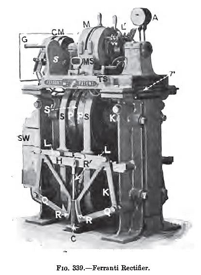 |
| Left: The Ferranti Rectifier: 1902
This rather intimidating machine was designed to generate DC to power circuits of electric arc lighting at a constant current, no matter how many arcs were connected. The current was controlled with a transformer that had a variable spacing between primary and secondary. A synchronous motor drove a rectifying commutator to turn the output of the transformer into DC.
"S,S are the two movable secondary coils, and P,P the two halves of the fixed primary; a separate fixed secondary winding being sandwiched in between at S’. The current induced in the latter is used for driving the synchronous motor M. The gun-metal frames supporting S,S run on ball bearings carried by the horizontal bar H; and these frames are geared together, through the links L,L, by the quadrant pieces Q,Q, and racks R,R, which engage with a corresponding rack cut on the upper portion of a counterpoise C."
CM is the rectifying commutator, driven by synchronous motor M.
Source of quotation: Electrical Lighting and Power Distribution by W Perren Maycock, Volume 2, p564-566. Pub Whittaker And Co, 1903
|
THE SIEMENS BROTHERS AND HALSKE BRIDGE RECTIFIER
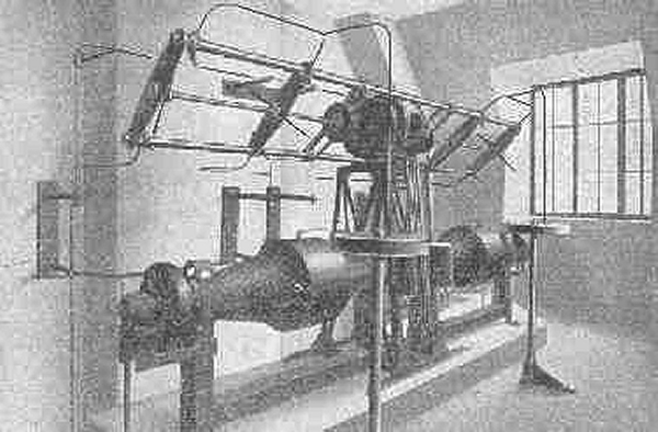 |
| Left: The Siemens Brothers and Halske Bridge Rectifier: 1916?
This image is of less than startling quality but it shows a remarkable machine built by Siemens Brothers and Halske to generate DC at 250 kV for X-ray work. With suitable tubes it allowed the production of X-rays of 0.05 Angstrom, for radiotherapy of tumours.
The long cylindrical thing is the step-up transformer, composed of two 125k V units in series on a common iron core and with oil-filled secondaries. At the front and above are two chokes (the circular things on the vertical rods) to control sparking at the rectifier contacts. The synchronous motor is mounted on a stand above the transformer. An insulated shaft extends either side of the motor.
Mounted on both sides of the motor are two heavy wires at 90 degress to one another,
but one of the total of four wires is invisible owing to the angle and a support which obscures it. The wires in the 10 o'clock - 4 o'clock direction are most easily seen, but one wire at 7 o'clock can be seen just clear of the end support at the left front. The stationary electrodes of the bridge can be most clearly seen at the front of the array, where on the left hand side of the motor, two stationary electrodes are commoned at the top and connected to one of
the chokes by a downcoming vertical wire.
Location unknown. Date around WW1.
|
MECHANICAL RECTIFIER PATENTS
The following US patents have been located:
1950 US 2.502,932 "Mechanical Rectifier" by Eduard Diebold. Assigned to Boveri & Cle, Baden, Switzerland.
1953 US 2,651,750 "Mechanical Rectifier" by Floris Koppelmann and Helmut Böhm.
Both patents are long and complicated and are aimed at three-phase operation.
MECHANICAL SWITCHING FOR HIGH VOLTAGE
Historical rectifier technology had limits on the voltage it could handle as well as the current. When really high voltages were needed, mechanical switching was again resorted to, though now we are talking about the multiplication of DC voltages rather than the rectification of AC. A classic application was the energising of electrostatic precipitators, (a long and detailed Wikipedia page) which removed fine particles from power station exhaust gases and other chemical processes, but the idea is much older than that, going back to Gaston Plante who is best known for his early work on lead-acid batteries in 1859.
THE PLANTE RHEOSTATIC MACHINE
 |
| Left: Plante voltage multiplication system: 1898
Plante referred to this as his 'Rheostatic Machine' though why is currently uncertain as it seems to have nothing at all to do with rheostats, which are a form of wire-wound variable resistor.
The machine consisted of a bank of mica capacitors that were charged in parallel but discharged in series, multiplying the voltage by the number of capacitors. The switching was done by means of a long rotating commutator. The illustration shows horizontal bars on it for charging the capacitors in parallel. On turning the handle, the capacitors were connected in series by wires passing through the commutator, and the output voltage was delivered to the spark gap above the machine.
In an article in Nature Plante spoke of "...a secondary battery of 800 couples which I at present possess." Assuming these were lead-acid batteries, the voltage from each would have been in the range 1.8 to 2.1 V. The total voltage of these cells in series can therefore be estimated at some 1600 V with a hefty current capacity- a situation to be treated with considerable respect.
Plante goes on: "The tension of a secondary battery of 800 couples is not necessary to produce marked effects with this apparatus. By putting in action only 200 couples, we have sparks of eight millimetres..." The breakdown voltage of dry air is 30 kV/cm, which implies a voltage here of 24 kV. If the low-voltage input was 200 x 2 V, that works out as exactly 60 capacitors. There seem to be fewer than that shown in the drawing.
The Plante machine was a mechanical precursor of the most ingenious Marx Generator, in which the switching is done by spark gaps. The Marx generator was proposed by E Marx in 1923.
Source: Nature 9 May 1878
|
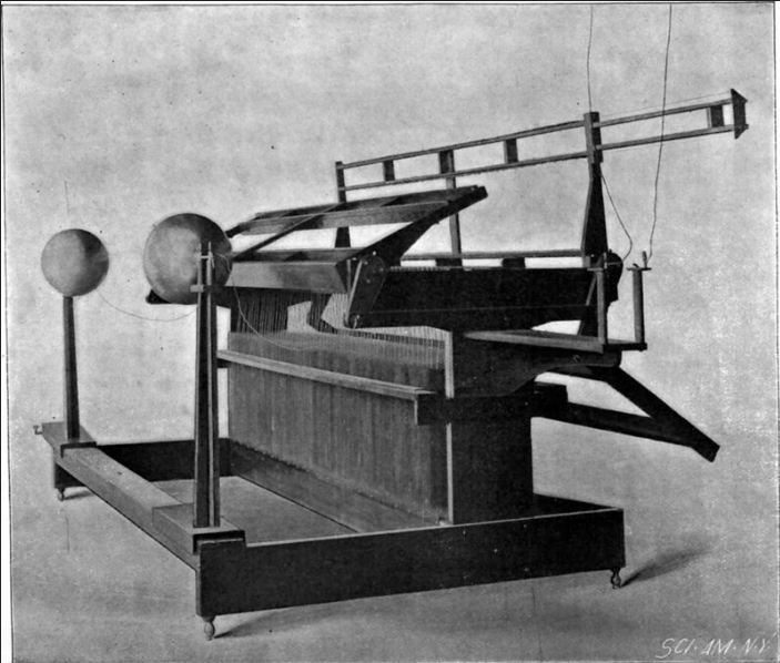 |
| Left: Plante voltage multiplication system: 1898
This shows a different form of the machine, and seems to be derived from a photograph. The bank of capacitors is clearly visible, but where is the commutator?
The low voltage input is at the right, and the output spark gap (composed of two big balls) is on the left, with a wire running to each ball.
Source: Scientific American for 15 Jan 1898
|
THE LODGE-STURTEVANT SYSTEM
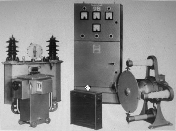 |
| Left: Lodge-Sturtevant rotary rectifier system
Described in the original caption as a 'later development'.
Picture courtesy of Malcolm Richards
|
I am very grateful to Malcolm Richards for the following information:
"With regard to mechanical rectifiers, you might be interested to know that they were still used in power stations right up to the 1980’s to produce high voltage DC for electrostatic precipitators. Each rectifier had an insulating disc several feet in diameter with contacts on the periphery, fed from a high voltage transformer and driven by a synchronous motor. Currents were in the high milliamp range with voltages up to 60 kV. Perhaps surprisingly, contact wear was not a serious problem. They have now, as far as I know, all been replaced by solid state rectifiers. Ozone production was something of a problem, and the rectifier rooms were thoroughly ventilated with electric fans."
"I recall that the rectifiers were fed from HV transformers via induction regulators, and the control circuits stepped up the voltage in increments until flashover occurred somewhere within the precipitator, which was detected and the voltage was backed off a little until the arc was broken. This process was repeated after a brief interval, so that the voltage was maintained at just below the flashover point. which depended, in part at least, on the varying composition of the flue gases. The later electronic controls were much faster acting and more sensitive, and once this had been demonstrated, the mechanical rectifiers were doomed. I worked at Ironbridge power station, and I think the last ones went about 1982. They were very impressive to watch in action, with a strong smell of ozone and the crackling of arcs. The makers of the ones at Ironbridge were Lodge-Cottrell of Birmingham, the Lodge of course being Sir Oliver Lodge."
|
I received the following extra information from a past employee:
"I would like to make a small correction to the article by Malcolm Richards."
"The rectifiers where fed by voltage regulators (similar in principle to "Variacs") One such is shown front left in his picture."
"Induction regulators (Transductors) were never used commercially, chiefly because the rectifier synchronous motor could not easily follow the phase change of the transductor output. We did experimentally drive rotary rectifiers from transductors but abandoned the rotary rectifier to develope silicon rectifiers."
|
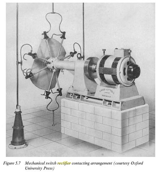 |
| Left: Lodge-Cottrell rotary rectifier system
This is something of an enigmatic picture. (an image search yielded nothing) The black cones are presumably the fixed contacts and seem to have spark-gaps between adjacent pairs. The arms carrying the moving contacts are not equally spaced, which is probably significant, but the reason is currently unknown.
Note the name Lodge-Cottrell on the motor pedestal.
I can report that Lodge-Cottrell are still in the electrostatic precipitation business.
|
OTHER MECHANICAL RECTIFIERS
THE DYNAMO:
The commonest mechanical rectifier is the commutator of any dynamo. The Morton Rotary Rectifier (see above) worked on this basis, driving the commutator with a synchronous motor.

.jpg)