Updated: 8 Apr 2010
More on efficiency


The Electromagnetic Engine |
Updated: 8 Apr 2010
|
This page is dedicated solely to electric engines that convert reciprocating to rotary motion by a crank or equivalent. There were many, although the reciprocating electric engine proved to be the deadest of technological dead ends. Only a small sample are shown here.
Most electric engines were essentially solenoids that pulled a piece of iron into their centre when energised. This was coupled by a connecting rod to a crank and flywheel, just as in a steam engine. A set of contacts switched the solenoid current on and off at the appropriate times so the iron could be drawn out again by the flywheel and continous motion obtained.
THE HENRY ENGINE: 1831
The American scientist Joseph Henry (1797-1878) constructed a small electromagnetic engine, with a reciprocating beam. He called it as a "philosophical toy", and there was certainly no intention of getting useful work out of it. It was first described in American Journal of Science, 1831, Vol 20 p342. In a British journal Philosophical Magazine in 1838, F Watkins examined Henry's invention in detail and described it as the first cyclic electric motor, ie one that continued working without manual switching or resetting.
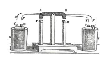 | Left: The Henry magnetic rocker: 1831
|
 | Left: The Henry magnetic rocker: 1831
|
Joseph Henry did much work on electromagnetism and in 1893, his name was given to the standard electrical unit of inductance, the Henry.
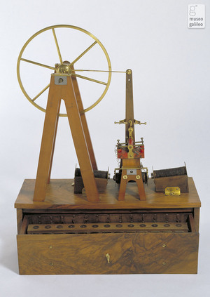
DAL NEGRO'S ENGINE: 1832
Salvatore dal Negro, an Italian, built in 1832 the first electric engine with a quantifiable power outout. Rotary motion was obtained from a pendulum with a rachet device, and it could lift 60 grams by 5 centimeters in one second and so hence developed nearly 30 mW of mechanical power.
Dal Negro described his experiments in a letter in April 1832 and later in a scientific paper: "Nuova Macchina �lettro-magnetica" in March 1834. His machines are stored at the Museum of the History of Physics at the University of Padua. Unfortunately, they are not displayed.
 | Left: dal Negro's magnetic pendulum: 1832
|
THE JACOBI ENGINE: 1838
In 1838 or 39, the Prussian physicist Moritz Jacobi constructed the world's first electrically propelled boat, using a a reciprocating solenoidal electromagnetic engine of about 1 HP to drive two paddlewheels. It was publicly demonstrated it on the river Neva in Russia. Electric power came from a bank of chemical batteries, the fumes from which (probably nitrogen dioxide, but this detail is so far unclear) were so copious that the experiment had to be prematurely terminated.
However, Jacobi was back the next year with the same boat, but a better battery bank, a fifth the size of the previous one, and presumably less likely to poison its owner. It appears that the reciprocating engine had been replaced by a much more effective rotary motor. The 28-foot boat managed an average speed of 3 mph while carrying 12 or 13 passengers.
THE MAGRINI ENGINE: ca 1840
Luigi Magrini (1802-1868) was born in Udine, and obtained a degree in mathematics from the University of Padua in 1825. He held the chair of Physics at Florence, Italy, and worked with Leopoldo Nobili, the thermopile experimenter. See here for more on thermopiles
His reciprocating electric engine is in the Museum of The History of Science at Florence. Unfortunately photography is not permitted in the museum, so I am unable to show you the picture below.
 | Left: The Magrini reciprocating electric engine: circa 1840
|
THE BOTTO ENGINE: 1834
Guiseppe Domenico Botto (1791-1865) was Professor of the University of Turin. His electric engine used swinging coils mounted on a sort of pendulum.
 | Left: The Botto electric engine: 1834
|
THE PAGE ENGINE: 1844
Charles Grafton Page of the USA was an early electrical pioneer, and also a physician, patent examiner, patent advocate, and a professor of chemistry.
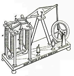
| Left: Page's first electric engine: 1838
|
Above: The Page reciprocating electric engine: 1844. Another inexpert drawing, unfortunately.
Here page very clearly took his inspiration from horizontal steam engines.
The Naming Of Parts:
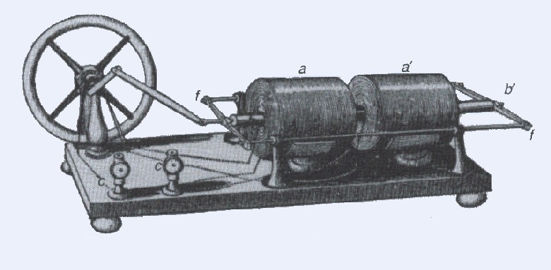
This is a later design, which Page called his 'axial engine'. Two solenoids are placed in tandem to drive the flywheel through a conventional crank, alternately pulling in two cylindrical armatures, and working on both directions of movement in the same fashion as a double-acting steam engine. The current through the solenoids was apparently switched by a commutator on the crankshaft, though this detail is not very clear in the drawing.
The use of solenoids, rather than magnetic bars waving i the air near magnets, was great step forward in efficiency.
Page later, in 1851, built an electromagnetic engine that developed 16 horsepower; this reached 19 mph when used in a battery-powered electric locomotive on the Baltimore and Ohio railroad. it is not confirmed that this was of the reciprocating type.
THE DEPEOLE ENGINE: 1891
This patent is dated 1891, by which time it was very clear that electric motors should be rotary. Nonetheless, Charles J Van Depoele of Massachusetts thought it was worth taking out this patent.
He was almost certainly wrong.
THE JACHIM ENGINE:1995
The box 6 is a contactor that times the energisation of the solenoids.
Jachim cites a long list of patent references, from 1915 to 1993. The final patent was granted to Charles Wortham, (US 5,219,034) and it seems to indicate that Charles did not know what a solenoid was, and the idea of an efficient magnetic circuit meant nothing to him.
CONTEMPORARY ELECTRIC ENGINES
Here on Youtube a single-solenoid horizontal engine like that of Page's 1844 design.
Also on Youtube, an 8-solenoid V-8 engine. Apparently he has built a V-12 as well.
This webpage describes the practical construction of a (relatively) advanced solenoid motor with optical electric timing and forced-air cooling of the solenoid. Yes indeed!
This is only a very small sample of what can be found on Google; an image search is recommended.
APPENDIX ON DEEP TECHNICALITIES
The familiar rotary electric motor is usually a constant-reluctance design.
a,a'
Solenoids
b,b'
Armatures
c,c'
Electrical input terminals
f,f'
Yokes joining armatures to guide rods
Left: The patent drawing of the Depoele engine.
Mr Frank Jachim was not convinced that solenoid engines had nothing to offer. He was granted US patent 5,489,004 in November 1995 for a 'Electric Vehicle Solenoid Motor'.
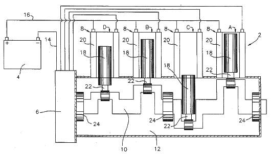
Left: The Jachim solenoid engine: 1995
Electric engines are still being made, though not for the serious production of power.
Solenoid reciprocating engines are example of variable-reluctance electric motors. Reluctance is a measure of how hard it is for a given electromagnetic induction to set up a circuit of magnetic flux- a kind of Ohm's Law of magnetism. If a magnetic system has moving parts these naturally take up a position that results in the greatest magnetic flux, ie a position of minimum reluctance.


