Gallery opened July 2005
Updated: 21 Nov 2017
Clockwork tram info added


Powered by Clockwork |
Gallery opened July 2005 |
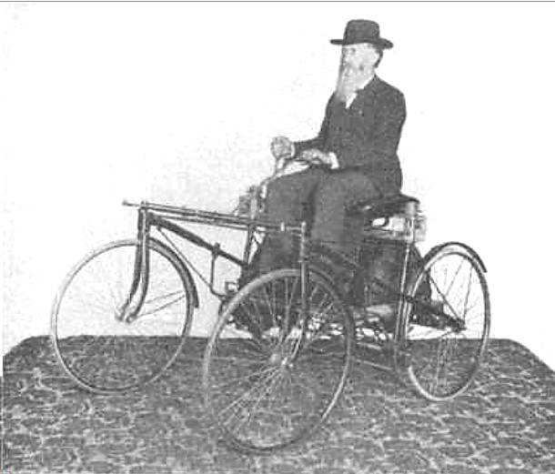
THE CLOCKWORK EXPLOSIVE BOAT: 1864
Robert Whitehead is well-known as the originator of that boon to mankind, the torpedo. He was born in Little Bolton in 1823, into a family of engineers. By 1864 he was manager of an engineering company in Fuime, near Trieste, which did work for the Austrian Navy. Whitehead and an Austrian Navy Captain, Giovanni de Luppis, collaborated on an unmanned self-propelled boat designed to blow up blockading warships. It was called the "Der Kustenbrander" ie The Coastal Fire Ship. Whitehead tried for several months to help Luppis with his invention but they failed to come up with a practical weapon, there being serious problems with the clockwork engine and the tiller steering.
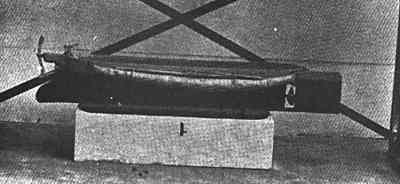 | Left: The Clockwork Kustenbrander
|
Regrettably I have so far found no details of the engine, but I strongly suspect it was very short on both power and endurance. Whitehead later used compressed-air to power his torpedoes; as with the clockwork tram described below, clockwork was superseded by air as the latter proved to be a much more effective "spring" for energy storage, despite the losses inherent in compressing air and throwing away the heat generated by doing it.
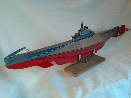 | Left: Clockwork model submarine by Neil Mclaren
|
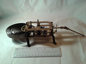 | Left: Clockwork motor for model submarine
|
THE CLOCKWORK TRAM: 1875
Unlikely as it may seem... it has at least once been seriously proposed to transport people by means of clockwork. Here is the only example I have found so far.
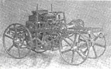
A clockwork tram was built by Thomas Middleton and Co, of Southwark, London, to the design of a Belgian, E H Leveaux. It was used to haul a tramcar at the Lillie Bridge depot of the Metropolitan and District Railway (London) in May 1875, reaching a maximum speed of 7 mph over a half-mile run. Experiments continued into 1876, but were then abandoned.
Leveaux received US patent 169,816 for a clockwork tram in November 1875; he was living in Hammersmith in London at the time.
 | Left: Clockwork-driven tram: 1875
|
The compressed-air trams used the same principle, in a sense, as the elasticity of the compressed air can be regarded as a sort of spring. They, however had a much greater range and were reasonably successful.
Thanks to Chuck Bencik for locating the patent.
CLOCKWORK CARS
Almost every conceivable form of power was used on early motor cars. Some stored energy rather than generating it (as in a petrol engine) and the most successful of these were electric cars, which carried around a heavy load of rechargeable batteries, as indeed they still do today. Less promising storage methods were carbonic acid (carbon dioxide) under pressure, and compressed air. Even less promising was the use of clockwork, where the power to be stored had to be applied in mechanical form rather than by filling a tank. Some intended power sources were either imaginary or incomprehensible; see the page Diverse Forms of Power in 1894.
 | Left: Clockwork car: pre-1895
|
 | Left: Clockwork car: 1890
|
Attempts to track down Mr Ingersoll Moore threw up only this intriguing fragment:
"ON a cold November evening in 1895, I went to the country to bring in a young cow. As I was leading her along, she took a notion to run, dragging and throwing me head foremost into a barbed wire fence. When I reached home an hour later, I found my face was cut in several places, a piece of flesh torn out of one cheek by the barbed wire, and one ear torn so that the lower lobe was separated and hung down.
"My wife and daughter, not feeling competent to handle the case at that time, called a Scientist healer. We tied a cloth over the wound to cover it up, and Christian Science did the rest. Four days later I went to work and kept right on as usual, with but little inconvenience. The ear came together, the cheek filled out, and the scar has already disappeared. � Ingersoll Moore, Bloomington, Ill."
The name is absolutely correct, and the date fits, but unfortunately all we learn is that Mr Ingersoll Moore was a a farmer and a Christian Scientist.
THE MECCANO CLOCKWORK MOTORS
To engineers of a certain age, Meccano holds some poignant memories. Clockwork motors were available to power the models. Here are a couple that I have.
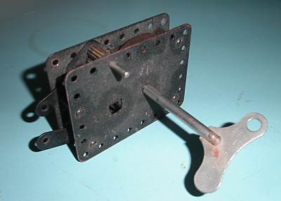 | Left: The big Meccano motor
|
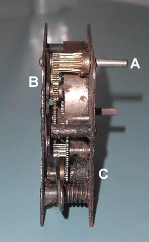 | Left: Inside the big Meccano motor
B: Reversing mechanism C: Governor |
 | Left: The small Meccano motor
|
For more on Meccano clockwork motors see here:
GRAMOPHONE CLOCKWORK MOTORS
One of the last places that clockwork motors held out was in driving gramophone turntables. This was convenient for picnics etc where electric power was not available. Garrard were the leading manufacturers of these motors.
Garrard and Company were originally jewellers, but in 1914 were asked to manufacture precision range finders for the British artillery. In 1918 a Mr H V Slade, who became General Manager, saw a need for quality spring wound motors for the fast developing gramophone manufacturing industry. The first model, The Garrard No 1 Spring Wound Gramophone Motor was produced and sales quickly followed. Development of the spring motor continued, and due to its manufacturing quality, silent running, and price, it was used by the major gramophone companies, notably Columbia, Decca, and HMV. (His Masters Voice), It was also used by lesser-known companies such as Lugton, Selecta, Coppock, Itonia and Thompson, and Diamond and Butcher. Garrard's policy was that the top model of every range should be the best obtainable on the market. The "Super" Gramophone motor was the first of these flagship products; it has been claime to be the best spring motor ever produced.
In 1926 Garrard began the development of electrical motors for gramophones,
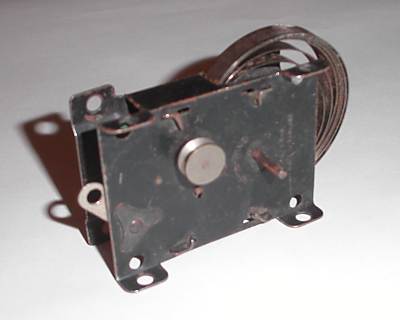
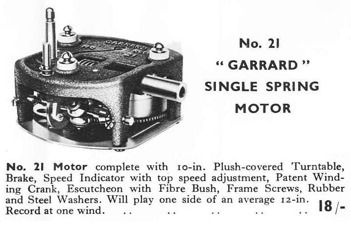 | Left: The Garrard No 21 clockwork motor
|
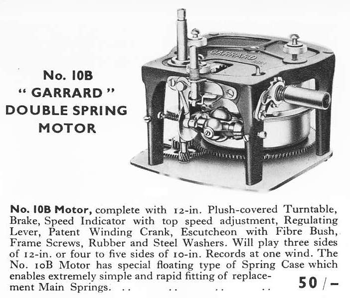 | Left: The Garrard No 10B clockwork motor
|
The Garrard leaflet includes a list of replacement springs- clearly spring breakage was not uncommon. It appears that replacement springs can stll be had from this company.
![]()

|