Gallery opened: Aug 2001
Updated: 28 June 2016
New pc, text fixed


Velox Boiler Locomotives |
Gallery opened: Aug 2001
|  
|
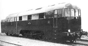 | Left: The French Velox boiler locomotive.
This was a 1937 reconstruction of an existing 4-6-0 locomotive by the Paris, Lyons & Mediterranean Railway. It was taken over by the French national Railways, and before the Second World War it was working express passenger trains up to 580 tons on the Paris-Dijon route.
Four-cylinder compound; boiler pressure 290 lb/sqin at 715 degF. |
A Velox boiler burns fuel oil or pulverised coal under pressure in a water-tube boiler. The pressure in the combustion chamber is about 35 lb/sqin, increasing the air density, and so making more oxygen available and allowing a higher firing rate. It contains only a small mass of water, so the boiler can raise steam from cold in 15 to 20 minutes. After stopping firing for an hour, apparently only 6 minutes were require to regain steam pressure.
Thinking about all that compressed air, you can probably see the way that this is going already. The Velox boiler requires an awful lot of ancillary equipment, all of which has to be carried around on the locomotive. The air compressor will use up a lot of power- which has to be available before you raise steam.
The Velox locomotive therefore carried the following around with it:
 | Left: Side view of the French Velox locomotive, with its tender |
Corridors within the streamlined casing allowed inspection of the machinery en route. The fuel, water and the auxiliary diesel-electric generator were carried in a 6-wheel tender.
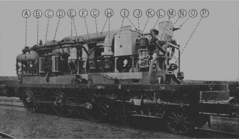 | Left: The internals of the French Velox locomotive
|
Key to photograph above:
A Auxiliary steam condenserG BlowerM Steam admission pipes
B Feedwater treatmentH Air ducts from blower to combustion chamberN Chimney
C Feedwater purifierI Sand boxesO Throttle valve
D Steam generatorJ Economiser (feed heater)P Reversing gear
E Gas turbineK Blower starting motor
F Air entry to blowerL Braking air pump |
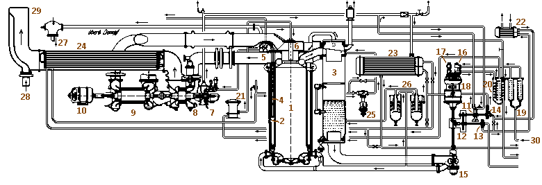 | Left: The steam circuit of the Velox locomotive.
|
Key to steam circuit diagram above:
1 Combustion chamber9 Air compressor 17 Lube oil pump 25 Controller
2 Evaporator 10 Electric motor 18 Electric motor26 Oil separator
3 Water separator 11 Steam turbine for pumps19 Fuel oil prefilter27 Superheated steam to HP cylinders
4 Superheater 12 Gearing 20 Fuel oil filter & heater28 LP exhaust
5 Superheated steam reservoir 13 Feed pump 1 21 Air/oil metering unit29 Chimney
6 Oil burner 14 Feed pump 2 22 Lube oil cooler30 Fuel oil from tender
7 Steam turbine 15 Circulating pump 23 Aux steam condenser
8 Gas turbine 16 Fuel oil pump24 Feed water heater |
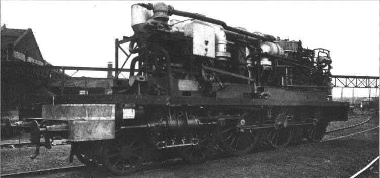 | Left: The internals of the Velox loco from the other side |
Starting procedure:
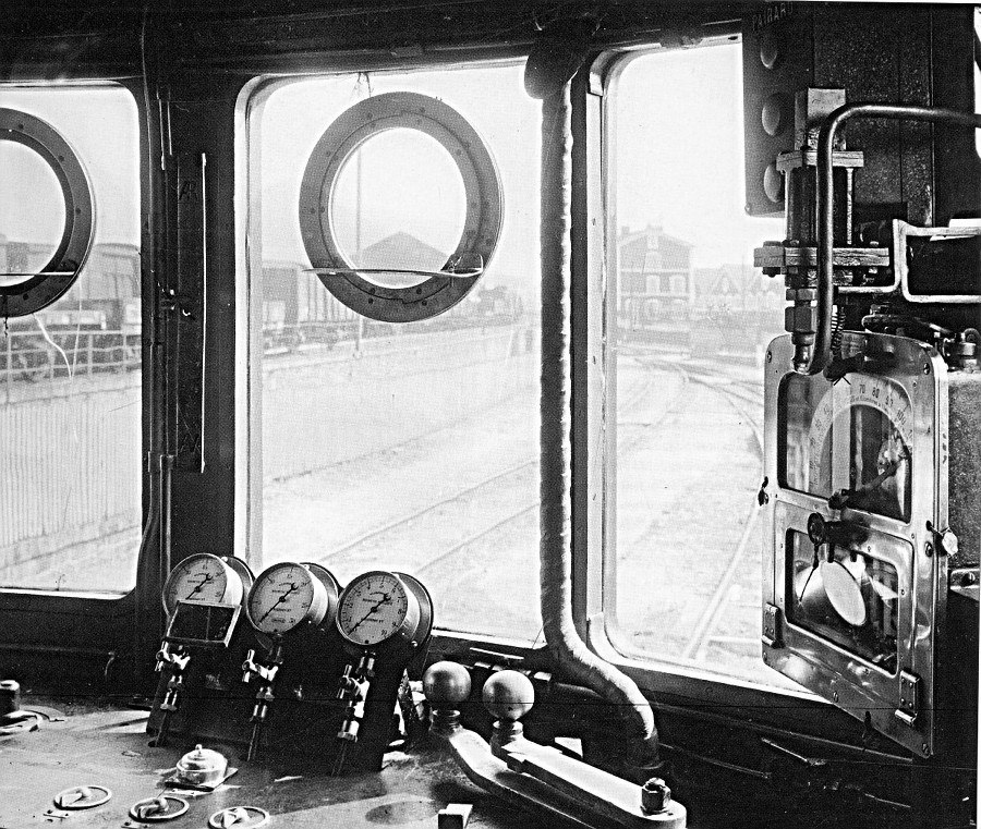 | Left: The French Velox boiler locomotive
The view from the cab. Three pressure gauges with their cutoff valves can be seen.
The instrument on the right is (I think) a lockable speed recorder.
|
Bibliography; Bell, 1946. Stoffels

  
|