Updated: 16 Apr 2016
New picture


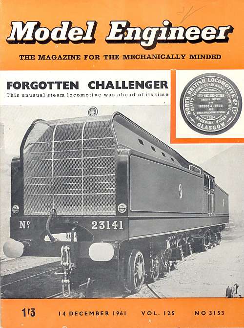
The Reid-MacLeod Turbine Locomotive. |
Updated: 16 Apr 2016 |
 | The front end of the Reid-MacLeod locomotive.
|
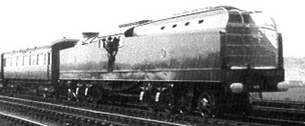
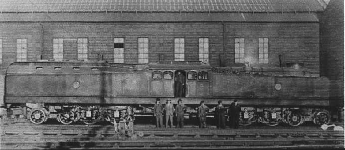 | Side view of the Reid-MacLeod locomotive
|
Each bogie had four axles, but only the two with the larger wheels were driven. The high pressure Ahead and Reverse turbines were mounted on the rear bogie, under the boiler; the low pressure Ahead and Reverse turbines were mounted on the front bogie, under the condenser. They were coupled to the wheels through two stages of reduction gearing, the first 8:1 double helical, the second 2.38:1 bevel gears, giving a total reduction of 19:1. A quill-drive protected the turbines from vibration and driving wheel displacement; the larger bevel wheels were keyed to a quill (ie a hollow shaft that surrounded the actual axle and could rotate independently to a limited extent) with discs at each end and three blocks. The axles passed through the quills, and the wheels were driven in either direction through three helical springs in compression, spherically seated in the blocks and in similar projections on the wheels themselves. The oil-tight gear casing- the whole motive power unit- was carried on six helical springs and constained by vertical guides. It therefore became a floating unit divorced from the displacement of the wheels.
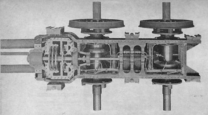 | The high-pressure motor unit of the Reid-MacLeod.
The first stage of gearing can be seen between the two axles; the photo is not very clear but there are two helical gears working in opposite senses to cancel end-thrust. Oil sprayers can be seen just above the pinions. |
The oil-tight gear cases were divided longitudinally for easy access, and there was forced lubrication. Steam at 180 psi and 700 degF (ie with 320 degF of superheat) fed the high-pressure impulse turbine. Like the low-pressure impulse turbine it developed 500 HP at 8000 rpm, corresponding to a running speed of 60 mph. A reversing turbine incorporated in each casing developed 70% of the power of the Ahead turbine. The turbines had three blade rings for forward and a separate single ring for reverse.
Steam from the high-pressure turbine was fed forward to the low-pressure turbine, and from there to the condenser.
 | Drawing of turbine bogie from the Reid-MacLeod USA patent.
(I haven't had time to read all the patent text yet) |
The engine was reversed by turning the control wheel which governed the direction and speed. Ahead admission was through two 3 in. double-beat valves, one opening after the other. Both were used for full steam admission. A single 4 in. valve was employed for reverse. The steam leaving the high-pressure turbine passed to the low-pressure turbine through receiver pipes, and thence to the air-cooled evaporative condenser. This consisted of two main groups of copper tubes, which could be sprayed with water; as it evaporated on the tubes cooling was greatly increased. Water was delivered in a fine spray from banks of jets at the intake end, and the moist air was discharged to the atmosphere. The spray jets were controlled by the driver to suit operating conditions. The exhaust steam ascended the tubes in the first group and descended those of the second and the condensate was withdrawn and discharged through the air-pump intercooler to the hot well under the cab by a rotary pump. A natural current of air was provided as the locomotive travelled condenser first; when this was not enough, a turbine-driven fan drew more air over the tubes.
From the hot well, the water was withdrawn by the boiler feed pump and delivered to the boiler through a feed water heater supplied with exhaust steam from the forced lubrication, boiler feed and Westinghouse brake pumps. The boiler was the conventional locomtive type with a superheater. Because of the condensing operation, there was no blastpipe and either forced or induced draught was used. A steam turbine driven fan delivered forced draught air into the ashpan when the fire-door was closed; when it was opened an interlock on the fire-door latch sent the air up the chimney instead to induce a draught. This dual arrangement was designed to prevented blow-back of fire through the fire-door. Reversal from induced to forced draught was automatic on the closing of the fire-door. For the fireman's sake, one can only hope that this system worked promptly and reliably.
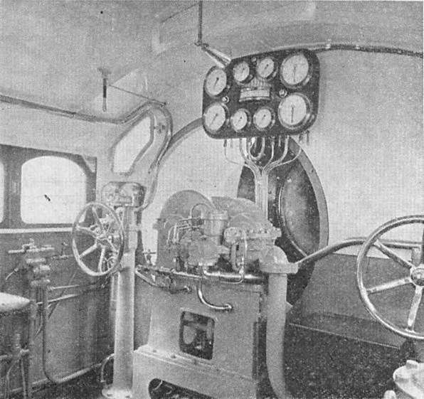 | Inside the cab of the Reid-MacLeod locomotive.
|
To start the engine:
Steam was raised, the forced lubrication pump was started and the auxiliaries (forced draught fan turbine, condensate and sprayer pumps) were brought into action. The main boiler stop valve was opened; the Ahead and Reverse valves were opened to warm up the turbines; the main steam stop valve was opened to the second stage; the main and auxiliary drains were closed; the stop valves to the turbine glands were opened; and the condenser fan turbine was started up. This procedure took seven minutes after steam had been raised.
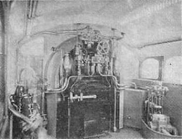 | Inside the Reid-MacLeod locomotive.
|
The locomotive was shown at the British Empire Exhibition of 1924, a long time before the first trials in 1926.
![]()
THE TRIALS
On initial testing a tractive effort of 15,000 lb was recorded on a dynamometer at the Hyde Park works.
A journal of the day reported on an early test:
"On reaching the engine shed we found steam up at 176 lb pressure, with a vacuum of 27 inches in the condenser. On moving the control wheel a short amount in the ahead direction, the locomotive drew slowly out of the shed and proceeded towards the siding points. She was run backwards and forwards several times before a clear road to the siding was secured. On reaching the siding a goods train of 280 tons was coupled up.
The rails were very greasy and the wheels slipped badly, but the engine drew the train steadily, and several trips to and fro of 300 to 400 yards were made. The wagons were then uncoupled and manoeuvring tests were executed, the engine being reversed by merely turning the control wheel in the desired direction and without stopping the turbines."
The last statement is clearly wrong. Since the ahead and reverse turbines were fixed to the same shaft, they must have stopped before starting to turn in the opposite direction.
More ambitious trials took place between March 1926 and April 1927. The first Glasgow-Edinburgh trial, with just two coaches coupled, had to be given up at Greenhill because of trouble with the condenser circulating pumps.
Extended tests were held on the LNER on 28 March 1926, when it was noted that the "almost entire absence of vibration, oscillation and rail pounding was a distinct feature in the locomotive and coaches." features which "particularly impressed the leading railway officials present."
A second run, intended to be Glasgow-Edinburgh-Glasgow suffered axlebox problems on the outward trip, and on the return run to Glasgow it suffered a turbine failure; apparently it never ran again. Perhaps it had already become clear that it was not a viable concept in locomotive design.
 | Another rare picture of the Reid-MacLeod. Sorry about the poor quality.
|
 | Left: The Reid-MacLeod at Waverley station, Edinburgh.
|
 | |
Above: The Reid-MacLeod at Springburn, Glasgow
|
![]()
THE VERDICT
It has been said that the engine was under-boilered, but it is very likely that the ultimate cause of failure was simply that turbines are only efficient at or near one design speed. This is fine in power-stations, but not in a locomotive where mechanically-coupled turbines have to run at very variable speeds. It appears that for this reason, the Reid-MacLeod locomotive expended enormous amounts of steam when starting from rest.
For many years the locomotive stood in her maker's works, rusting and neglected. It was eventually broken up to make room for air-raid shelters in the early days of WW2.
THE PEOPLE
The Reid in Reid-MacLeod was Hugh Reid, Deputy Chairman and Chief Managing Director of the North British Locomotive Company. For a potted biography see The Reid-Ramsey Turbine-Electric Locomotive
The MacLeod was James MacLeod, a Glasgow turbine expert. Reference to the 1925 patent shows that he spelt it MacLeod rather than McLeod, and this page has been altered to reflect that.
![]()

|