Opened Mar 2001
Updated: 4 Dec 2016


The Norfolk & Western Steam-Turbine-Electric. (USA) |
Opened Mar 2001
|  
|
 | Left: The Norfolk & Western steam-turbine-electric, built in 1954. It was numbered 2300
|
The locomotive carried the name "Jawn Henry", a reference to a legendary black construction worker who pitted his manual hammer and drill against a steam drill. According to the story, he just managed to beat it but collapsed and died shortly afterwards. Not a good omen, perhaps...

|
Above: General layout of Norfolk & Western steam-turbine-electric |
The front part of the engine was composed of a forward electrical compartment and a 20-ton coal bunker. The boiler was placed after the driver's cab, then came the turbine and generator in the power compartment, and finally a rear electrical compartment. The tender carried 22,000 gallons of water but no coal.
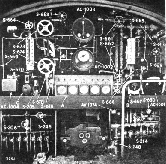
 | Left: The front of the boiler, in the rear of the driving cabS-205 - Steam Jet Control Valve S-206 - Master-Stoker Jets S-214 - Master-Cab Steam S-245 - By-Pass-Stoker Jets S-248 - Slicer Jet Steam S-613 - Auxiliary Steam Vent S-629 - By-Pass-Aux. Steam Reducing S-661 - Gauge Glass Shutoff - Top S-662 - Gauge Glass Shutoff - Bottom S-664 - Superheater Pressure Shutoff S-665 - Meter Shutoff (Line - AC-1001) S-666 - Meter Shutoff (Low - AC-1001) S-667 - Meter Shutoff (High - AC-1001) S-669 - Meter Shutoff (High - AC-1004) S-670 - Meter Shutoff (Low - AC-1004) S-673 - Gauge Glass Shutoff - Top S-674 - Gauge Glass Shutoff - Bottom S-678 - Water Column Blowdown S-679 - Gauge Glass Blowdown S-680 - Left Gauge Glass Blowdown S-683 - Boiler Drum Vent AC-1001 - Water Level Controller AC-1002 - Superheater Pressure Controller AC-1003 - Air-Fuel Ratio Controller AC-1004 - Superheater Flow Controller AV-1074 - Grate Drive Control Cock A - Boiler Front Gauge Panel B - Tender Tank Level Gauge C - Bell |
 | Left: The turbine0PERATOR'S MANUAL NO. STE-1. 4500 HP Steam Turbine Electric Freight Locomotive with Dynamic Braking |
Naming of parts for illustrations above and below: |
 | Left: The turbine and generator |

  
|