Updated: 30 Oct 2018
Links updated, tidied up


Updated: 30 Oct 2018 |
|
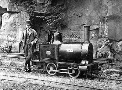 | Left: Arthur Heywood and his first narrow-gauge locomotive Effie.
Sir Arthur died in 1916. |
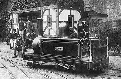 | Left: The narrow-gauge locomotive Ella.
|
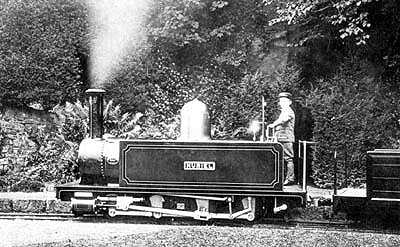 | Left: The narrow-gauge locomotive Muriel.
|
The Duke of Westminster commissioned Heywood to construct a 15-inch gauge estate railway at Eaton Hall, Cheshire, which opened in 1896, carrying coal, timber and bricks. This closed in 1947.
Sir Arthur died in 1916.
 | Left: The radiating gear of Locomotive Ella. This was designed in 1877 and built in 1881.
|
The details of Heywood's four engines are given here:
| EngineNo. | 1 | 2 | 3 | 4 |
| Name | Effie | Ella | Muriel | Katie |
| Built | 1875 | 1881 | 1894 | 1896 |
| Diameter of cylinders - inches | 4 | 4.875 | 6.25 | 4.625 |
| Length of stroke - inches | 6 | 7 | 8 | 7 |
| Diameter of wheels ... | 1 ft. 3/8. | 1 ft. 1 1/2 | 1 ft 6 | 1 ft 3 |
| Length of wheel-base | 2 ft. 6 in. | 4 ft. 6 in. | 6 ft. | 3 ft. |
| Number of wheels (all coupled) | 4 | 6 | 8 | 4 |
| Length of boiler | 4ft.6in. | 6ft. 6in. | 8ft.3in. | 5ft.8in. |
| Diameter of boiler | 1 ft. 10in. | 2 ft. 1 in. | 2 ft. 1 in. | 2 ft. 1 in. |
| Length of firebox (flue) | 1 ft. 9 in. | 2 ft. 3 in. | 3 | 2ft. 3in |
| Diameter of firebox | 11 in. | 1 ft. 3 1/4 in. | 1 ft. 3 1/4in. | 1 ft. 3 1/4in. |
| Number of tubes (brass) | 23 | 57 | 57 | 57 |
| Heating surface | 23 sq. ft. | 70 sq. ft. | 91 sq. ft. | 53 sq. ft. |
| Grate area | 1.25 sq. ft. | 2.12 sq. ft. | 3 sq. ft. | 2.12 sq. ft. |
| Capacity of tanks | 18 gals. | 50 gals. | 84 gals. | 49 gals. |
| Working steam pressure | 125 lb | 160 lb | 160 lb | 160 lb |
| Weight in working order | 1 ton 3 cwt. | 3 tons 15 cwt. | 5 tons. | 3 tons 5 cwt. |
| Co-efficient of adhesion 145 lb pressure | 3.6 | 4.7 | 4.5 | 4.9 |
| Railway | Duffield Bank | Duffield Bank | Duffield Bank | Eaton Hall |
| Fate | Scrapped 1894 | Scrapped 1923 | Converted 1926 | Sold 1919 |
Ella, Muriel and Katie were sold to the Ravenglass & Eskdale Railway narrow-gauge railway in 1916-17. This line opened in 1875 using 3-foot gauge, closed in 1913, then re-opened using Heywood's 15-inch gauge in 1915. It is still running today as a pleasure line, and one of the locomotives River Irt is a conversion of Muriel.
THE BOOK "MINIMUM GAUGE RAILWAYS"
The extract below is taken from the 1898 edition of A P Heywood's book "Minimum Gauge Railways", first published in 1881.
"The first locomotive put upon my line was completed in 1875. This engine was constructed, not so much as a model of what a small locomotive should be, as to provide the requisite motive power for the experiments I desired to carry out. No great care was, therefore, observed in the details, and in its construction a good deal of material which happened to be at hand was utilized to save time and expense; this much in excuse of the want of proportion in some of the dimensions, which will be found in detail under the head of No. 1 in the table of locomotive dimensions on page 81.
The boiler was of the launch type, a cylindrical shell with a cylindrical fire-box terminating in tubes. This pattern of boiler, though giving less heating surface for its size than one of ordinary locomotive design, has the great merit of having no fire box projecting below the barrel, thus enabling the over-hang of the frame beyond the wheel-base to be equalized at each end, a matter of the first importance in small tank engines. Its low first cost and the ease with which it can be kept in order are additional advantages. So well was I satisfied with the working, that in the four boilers since designed for my locomotives I have adhered to the original plan, which was copied from some shunting engines made by Mr. Ramsbottom for the London and North `Western Railway. I go so far as to think that, without getting rid of a depending fire-box, no really satisfactory tank engine can be constructed for a small gauge railway unless idle wheels are introduced, a proceeding that cannot too strongly be deprecated. The gradients, which are almost invariably the concomitants of these small lines, make it essential that the whole of the available weight should be utilized for adhesion.
The difficulty of carrying on four wheels a boiler of sufficient length for a more powerful engine, and the unsuitableness of an ordinary six-coupled engine to the sharp curves in which narrow-gauge lines generally abound, led me, in 1877, to work out a design by which the wheelbase of an engine of the latter type could be made to accommodate itself to any required degree of curvature. At this time I was in communication with officers engaged in promoting a scheme for an army field railway, where great power conjoined with perfect flexibility was essential. As the result, I constructed the engine of which the dimensions are given under No, 2 in the table, this being put to work in 1881. While avoiding the complication of the double-bogie system, this engine possesses most if not all, of its advantages. It is six.coupled in the ordinary way, the axles having outside bearings and cranks. The wheels, of cast steel, are not fixed upon the axles, but each pair is keyed upon a cast iron sleeve, through which the axle passes. The sleeve upon the middle axle is capable of sliding 1 in. in each direction laterally, but cannot revolve upon its axle thus, when the engine reaches a curve, the arc of the rail draws the middle wheels on their sleeve to an amount equal to the versed sine of the arc, without interfering with the rigid position of the axle.
The leading and trailing pairs are likewise mounted on sleeves, but here the connection of the sleeve with the axle is by means of a ball joint at the center, so constructed as to leave the sleeve free to radiate in any direction, but obliging it to revolve with the axle. The middle sleeve is so connected by external hoops and links with the leading and trailing sleeves that, when the former makes a lateral diversion, the two latter are radiated precisely to the required curve, providing it is within the limit of the travel of the middle sleeve, which, in this case, is arranged for a radius of 25 ft. This engine excited considerable interest among visitors to my railway at the time of the Royal Agricultural Show in Derby in 1881, but the opinion was expressed that the arrangement would not stand hard work. A few years later, however, when some officers of the Royal Engineers were trying the engine with a view to adopting the plan on the military railway at Chatham, they subjected it to very severe tests, loading it up steep inclines to its utmost capacity; stopping it with the steam brake almost dead when traveling at various speeds and over the most awkward places ; and, finally, giving it a fifty mile run with all the load that could be got together, at an average speed of seven and a half miles an hour, stops being made for water, &c., for twelve minutes in each hour. This was followed, shortly after, by a continuous run with a similar load for an hour and thirty-five minutes, the extreme limit to which the water in the tanks would hold out.
There was no heating of any part during the trials, nor failure of any kind. After eight years work, chiefly on gradients of 1 in 10 to 1 in 12, where sand has to be used freely, the engine came into the shops to be overhauled. During this time there had been no mishap or breakage whatever, nor had a wheel ever left the rails, except on one occasion in descending the steep incline, when, owing to the slippery state of the rails, and sand failing, the engine slid away and left the road less than an hour, however, sufficing to get it running again.
On removing and examining, shortly after this, the working parts of the radiating gear, they were found in perfect order, the tool marks being still visible in the ball joints; and in August, 1895, the engine, which was then sent over to do the ballast work on the Eaton Railway, where it worked for thirteen months, showed still a clean bill of health. The engine is now rebuilding, and it is proof of the excellence of the radiating gear that this part is being put together again without re-adjustment of any kind. There is thus no doubt of the success of this radiating principle.
This engine is fitted, as already noticed, with a steam brake, which can also be applied by hand; but the latter alone is far too slow in action for the abrupt stops necessary on a line like mine.
The space between the frames being occupied by the radiating arrangements, the valve gear is necessarily outside, and, to avoid overhung eccentrics, I designed a modification of one of Mr. Charles Brown's Swiss valve gears, which are also the parents of what is known in this country as Joy's gear. I venture to think that my plan, in which nothing projects below the connecting rod, is better suited to small engines where the motion is almost always near the ground than any yet produced. The gear is extremely simple, and has worked without any trouble; the only setting required being the adjustment to length of the valve spindles, and the setting of one fixed center on each side of the engine.
The springs consist of rubber pads placed between the axle-box and the horn-block. They are simple to fit, take up no room, never get out of order, and last many years. I have no steel-carrying spring on any of my stock.
The safety-valve spring is entirely within the boiler, so that it cannot be tampered with or injured by accident.
The connecting-rod brasses are peculiar. In order to avoid twist to the slide bar when the driving axle, owing to inequalities in the road, fails to preserve its horizontal parallelism within the frame, the brasses are shaped circular, so as to turn slightly in their straps, the latter being bored out in the direction of their length instead of slotted. This plan not only relieves both crank-pin and slide-bar of torsion, but also forums a much more rigid union between the strap and the rod end.
The steam jet is worked by the regulator handle, the valve being so arranged that when the handle is moved beyond the point at which steam is shut off, the jet is opened. A spring stop prevents the jet being opened inadvertently. Thus when steam is put on, the jet is by the same action closed, steam is saved, and two motions are performed in one.
An important point in this, as in all steam locomotives I have built, is that the overhang at the two ends is equal, and the weight also on both heading and trailing axles practically the same, when the driver is on the foot plate. A further arrangement of value is that in all my engines the cranks are counter-balanced. It is impossible to effect the counter-balancing on the wheels, nor, even if feasible, will the result be so good, as counter-balance weights on the wheel are not at the same distance from the axle center as the disturbing weights, and therefore not equable in their effect at different speeds.
This engine was built for tractive power, not speed, and eighteen miles an hour is the highest rate registered over the short straight course available. The previous engine, with 15.5in. wheels, recorded a speed equal to 28 miles an hour, the time being in both cases taken over a measured distance with a stopwatch. About 11 miles an hour is the usual average speed with passenger cars, which, owing to the severe curves, it is not deemed wise to exceed.
The net cost of the engine under consideration was Ł809, exclusive of drawings and patterns. At the time it was built a joiner and occasionally a laborer were my only assistants; the work consequently proceeded but slowly, occupying altogether two years and a half. Reducing the time to hours, the whole of my own labour was almost precisely equal to that worked in one year by an artisan, and that of my assistants together to about half the amount. This includes the time occupied in moulding, for all the castings were made on the premises, within the exception of the steel wheels.
The boiler, frame-plates, and some of the brass fittings, were purchased, but the whole of the machine work and fitting was executed on the spot. The cost of all material, the hours of labour and engine power, interest on tools, &c., were all carefully booked, and it will probably not be far from a fair trade price for the engine if 10 per cent for drawings and patterns, and 20 per cent for profit, are added to the cost given above, thus bringing the amount to about Ł400.
The working of the radiating gear of engine No. 2 proving so satisfactory, I elaborated the principle so as to apply it to an eight-wheeled locomotive. (No. 3 in the table.) In this case both of the middle pairs of wheels move the traversing motion already described, but, instead of the heading and trailing wheels being radiated from one central pair, the second pair of wheels radiates the leading pair, and the third pair of wheels the trailing pair, thus forming a mechanism practically equal to a double bogie. By this arrangement an eight-coupled engine is obtained capable of passing round curves as severe as may be necessary. In the present instance, the travel is constructed for a minimum radius of 25 ft. The details of the engine are similar to those of No. 2, but numerous improvements have been effected, into all of which it would be tedious to enter. It may, however, be mentioned that the ends of all the crank pins are boxed in by the connecting and coupling rod brasses, to exclude dirt. A steam water-lifter has also been added, by which the tanks can be filled without delay during frost. The blast-nozzle is made adjustable by raising or lowering an internal cone.
Owing to the steep gradient before alluded to, it was impossible to get a fixed size of nozzle that would keep up steam with a light load on the level, without being so contracted as to lift the fire off the bars on the incline.
The boiler fittings have been made as symmetrical as possible, and circular nuts have been substituted for hexagon, as more easy to clean. The water-gauge glasses are put in through the top cock and fastened by a single cap nut, thus doing away with the usual external glands. The steam brake has a 5 in. cylinder, and the rigging is arranged to swing within the traversing wheels.
The locomotive for the Eaton Railway (No. 4 in the table) was built as an example of a four-wheeled engine for use where the traffic was small and the gradient reasonable. With the exception of radial axles, it is fitted up precisely as No. 3 it has not, however, been altogether a success. From the data of its hauling powers, it will readily be seen that there is no deficiency in this respect; indeed, the maximum load handled exceeded all my expectations. In its working, for now nearly two years, nothing has gone amiss, nor has there been any trouble. On the contrary, the engine has on all these points given full satisfaction. But it is with regard to its effect on the road that I have my doubts. The running is steady enough, and 20 miles an hour has been attained without undue oscillation, yet nevertheless the road suffers as it never suffers under the six and eight-wheeled engines. The long and short of my experience is that I should not again recommend a four-wheeler except for very short distances and low speeds. Nothing but the experience I have had with this engine could have impressed so forcibly on me the very distinct advantages of such a radial action as I have adopted in my other locomotives, which enables them to go round a considerably sharper curve than the four-wheeler within an ease and absence of grinding quite remarkable, to say nothing of the saving to the road by the distribution of weight over more points. The relief seems to be by no means so much in the lessening of the weight per axle, which is not very great; as in the increased number of points of support. I am well aware this is not a new discovery, but it has come home to me within a practical force that leads me to insist somewhat strongly upon its importance.
The whole of the foregoing locomotives have been entirely made in my workshops, with the exception of the boilers and steel castings. The former have been chiefly supplied to me of excellent workmanship by Messrs. Abbott and Co., of Newark, and the latter by the Hadfield Steel Foundry Co., of Sheffield. The wheels of such little locomotives, since speed is no object, should be kept as small as possible, and the stroke should be of the greatest length. The nearer the stroke can be extended to half the diameter of the wheel, the more successful will the engine prove on steep inclines. Good sand-boxes, front and back, of ample capacity are essential, but it is not advisable to fit any steam sanding apparatus, for, owing to the low position of the motion, a good deal of the sand will rebound into the joints and bearings, as I found by experiment.
Cabs on such small engines are to be avoided as unbearably hot in summer, dangerous in case of emergency, and inconvenient at all times on account of the contracted dimensions. A stout mackintosh is cheaper and far better for the driver.
A steam water-lifter is a convenience in frosty weather when the water supply above ground may be frozen up, but in summer the engine tanks get so hot from their proximity to the boiler that the water, which becomes lukewarm in the process of being raised by the lifter, is then very soon at a temperature which makes the action of the injectors precarious.
I may say that in all my locomotives I use Holden and Brooke's restarting injector, which, after experiment with many types, I find takes the hottest water and is in all ways most reliable. I place brass wire strainers in both steam and water-supply pipes close to the injector, which is invariably fixed below the tanks, so that when the injector is overheated the water will run through by gravity and cool it; a most important advantage."
HEYWOOD LINKS
Arthur Heywood and The 15-inch Gauge (book)
![]()
