Gallery opened: Mar 2001
Previous update 8 June 2012
Updated: 6 Sept 2025
Polish model added here


The Fontaine Fiasco
|
Gallery opened: Mar 2001 |

| Most of the locomotives in the Museum of Retrotech have had some degree of success, or at least been a brave try that yielded useful knowledge. The Fontaine concept, however, appears to be devoid of any redeeming features. It was designed by Eugene Fontaine, of Detroit. |
The engine was built with the driving wheels ABOVE the boiler, their tread pressing on and transmitting motion to the carrying wheels by frictional contact. The designer claimed this would increase the speed of the engine for the same boiler pressure, though why he should have thought so is a bit of a mystery; it would appear that all that has been introduced is another place for slipping to occur. The likeliest explanation is that he was trying to gear up the real driving wheels so they turned faster than the "air-wheels". Slightly larger driving wheels would surely have been an easier way to the same end.
The first Fontaine was built in March 1881 at the Grant Locomotive Works, of Paterson, New Jersey, with shop number 1491. A second was built by Grant's in June 1881, with shop number 1503.
These extraordinary locomotives with two wheels up in the air really were built and put into service. They were tried on all kinds of trains, but proved inferior in every respect to the ordinary engines of the same capacity. After many modifications- none of which helped much- both were rebuilt as conventional 4-4-0 engines at the Rome works in or about 1884.
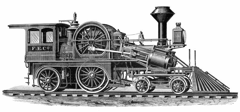
This picture (an engraving apparently taken from the photograph above, as was normal before photos could be printed) lends support to this theory. Some helpful soul has dotted-in the hidden parts of the wheels, showing that they do indeed step up the speed of the rail wheels, by a modest ratio of 1.4 to 1, if my measurements from the diagram are accurate. It does not seem worth the bother.
Further information just in (Abdill) gives the diameter of the upper drivers as 72 inches, the friction wheels they drove as 56 inches, and the diameter of the drivers actually on the rails as 70 inches. The step-up ratio was therefore actually 1.28 to 1. A pneumatically-driven system of "compound levers" could alter the pressure exerted by the top drivers on the friction wheels, which sounds rather sophisticated.
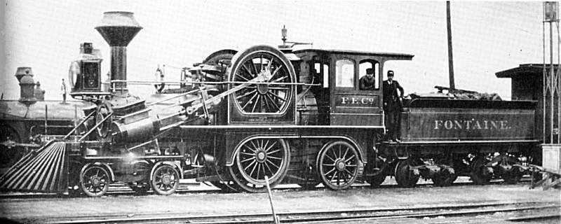
| A rare picture of the second Fontaine, shown here arriving at St Thomas, Ontario, Canada, in July 1881, for trials on the Canada Southern Railroad. Engineer Ike Deyell stands in the gangway, while Fireman George Westfall is leaning from the cab.
From A Locomotive Engineer's Album |
The cylinders were 17 x 24 in, the wheelbase was 23 ft 4 in, and the total heating surface (firebox + tubes) was 1033.5 sq ft. Total weight was 82,000 lb.
Info from Scientific American Supplement, 5th November 1881.
![]()
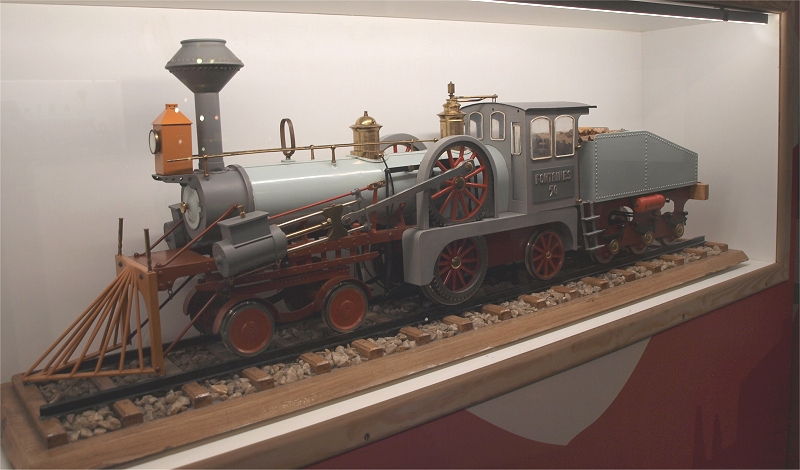
| This is a model of the Fontaine locomotive; it is in the Railway Museum in Warsaw, Poland. The museum has a website.It is not a very detailed model, but quite possibly the only model of a Fontaine locomotive ever built. Thanks to Jarek Jagielski for drawing this to my attention. |
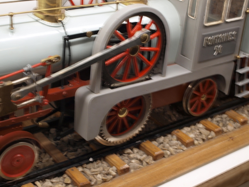
| This is perhaps the most interesting thing about the model. the constructor clearly decided that the Fontaine concept was hopelessly flawed, and added gearing between the upper and lower wheels.Thanks to Jarek Jagielski for drawing this to my attention. |

|