|
| The Brennan Gyro-Monorail
|
|
Gallery opened: Oct 2001
Updated: 20 Nov 2022
More pictures of trials added
|  
|
Having found a gyroscopic monowheel, the Museum of RetroTech now (15 Oct 2001) proudly presents... a gyroscopic monorail vehicle. Here is a truly wonderful piece of work.
The Brennan Gyro-Monorail was developed by the Irish-born Australian inventor Louis Brennan. (1852-1932) It was 40 feet long and weighed 22 tons, and was designed to carry 10 tons. Speed on the level was 22 mph.
The vehicle was balanced by two vertical gyroscopes mounted side by side, and spinning in opposite directions at 3000 rpm. Each gyroscope was 3.5 feet in diameter and weighed 3/4 of a ton each. They were enclosed in evacuated casings to reduce air-friction losses. The rotational axes were horizontal.
In the Gillingham tests the vehicle was fitted with two petrol engines. A small 20 hp unit powered the gyroscopes, drove an air-compressor (for braking?) lighted the car, and propelled it at slow speeds. A larger 80 hp engine was used for high-speed propulsion.
Brennan patented the concept in 1903; see patent No 27,212, with the unsensational title "Improvements in and relating to the Imparting of Stability to otherwise Unstable Bodies, Structures or Vehicles".
|
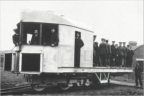
| Left: The Louis Brennan gyroscopic monorail, demonstrated to the press at Gillingham. Kent, on 10th November, 1909. Note the soldiers standing on the rear platform- apparently 40 of them.
The sleepers of the test track were 3.5 ft in length, laid 2.5 feet apart without ballast. The steepest gradient on the track was 1 in 13, and the sharpest curve had a radius of only 35 feet.
Note the double-flanged wheels to prevent slipping off the rail.
|
|
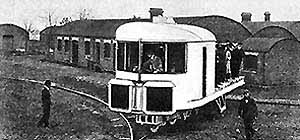
| Left: This looks like a test-track to prove you could back it in a wye and so turn it round.
If this machine was intended to pull wagons or coaches in the usual way, then there appears to be a problem. Surely each vehicle in the train would need its own gyro-balancing system, complete with power supply? Furthermore, it only take the momentary failure of one gyro system to cause the mother of all derailments. Not a war-winning weapon, I feel, and I imagine the War Office thought the same thing.
|


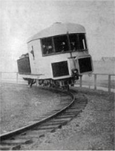
Above: Three pictures of a trial run with the machine loaded with civilian passengers.
|
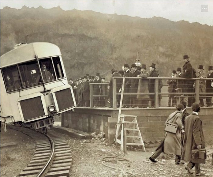
| Left: Trial run with gentlemen of the press scurrying out of the way: 1920?
This picture was supposedly taken on 17th Feb 1920, but that does not square with the date of 1909 given above. The steps are presumably for getting on and off the locomotive.
|
THE BRENNAN MODEL GYRO-MONORAIL
The first model was a very simple proof-of-concept of the 1903 patent. It was 2ft 6in long, 12in wide, and 10in long, with the whole of the internal space being taken up by the gyroscopes, motors and accumulators. No photographs of it are known to exist.
The second model was a one-eighth scale version of a proposed prototype for a monorail system, and still exists. It was used to demonstrate the gyroscope principle to the Royal Society in 1907. The electrically-powered model travelled along a single wire 6 feet above the ground, using grooved wheels, and maintained its balance despite its forward motion being repeatedly stopped, and the wire violently swung. On the strength of this, Brennan was granted a subsidy by the War Office to build the full-scale machine.
|
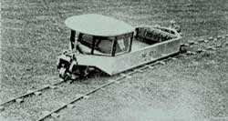
| Left: The Brennan model in action, using just one of a pair of rails.
The model was 6 ft long and 18 in wide, with a total weight of about 175 pounds. The accumulators to power the electric motors can be seen at the back of the load-deck.
|
A more detailed specification is given by Norman Tomilinson; (see bibliography) he says that it was 6ft long and 1ft 6in wide, with an unladen weight of 128 lb. Each gyroscope had a rotor of 5in diameter, spinning at 8000 rpm. The model was presented to the London Science Museum on 8 March 1946, by Robert Graham, Breenan's assistant and his helicopter pilot in later experiments that ran from 1920 to 1926. It then seems to have made its way from the Science Museum to the National Railway Museum at York.
|
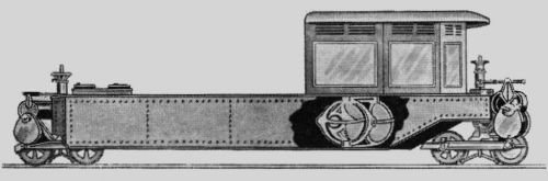
| Left: The Brennan model, with a cutaway showing the location of the two gyroscopes.
The cylindical structures just above the wheels at each end are electric motors for propulsion. There are two wheels at each end, coupled by a locomotive-type coupling-rod-and-crank arrangement.
|
|
| Left: How the two gyroscopes were mechanically coupled to utilise the precession forces.
When the car tilted, each gyroscope would try to precess by rotating round a vertical axis. This would not in itself stop tilting, as the torque is in the direction of steering rather than tilting. However, two gyros spinning in opposite directions produce precession forces in opposite directions, and when these are geared together as shown the result is a reaction on the horizontal shaft that counteracts the original tilt. Here the gyroscope axes are pointing out of the page.
I hope I've got that right.
|
|
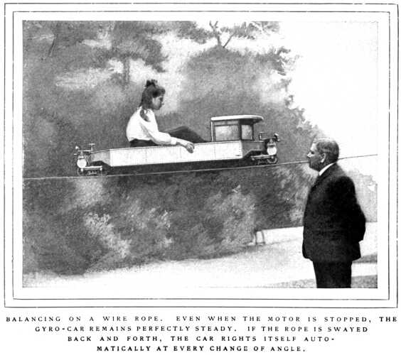
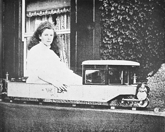
| Left: The Brennan model, carrying Brennan's daughter on an aerial wire.
From a certain lugubrious quality in her facial expression, one has to conclude that the young lady was not entirely happy with her situation
Source of picture currently unknown.
|
|
| Left: Another picture of the Brennan Daughtermobile
Nearer ground level, but still not looking very happy...
Gillingham (Kent County) Library
|
|
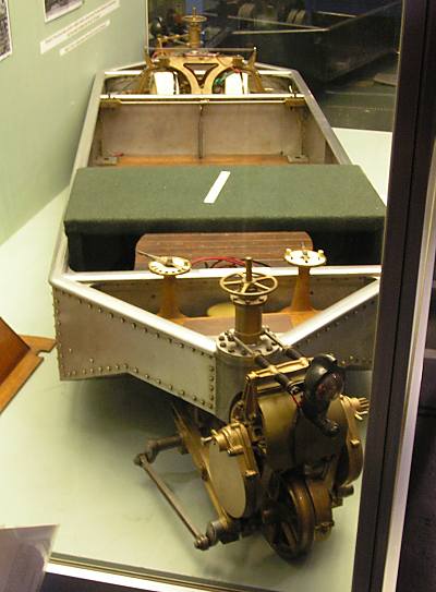
| Left: The Brennan model in the National Railway Museum at York.
Remarkably, the Brennan model still exists. It is shown here in a glass case at the National Railway Museum at York. The cab is missing, and the electrical wiring is no longer original, but otherwise it appears unaltered.
In the right foreground can be seen one of the electric motors, with its reduction gearing. At the bottom can be seen the coupling rod between the two wheels. The two dials on vertical shafts look as though they were for controlling speed (left) and forward/stop/reverse (right). The function of the handwheel above the motor pivot is unknown; possibly it controlled some sort of friction damper. The accumulators were mounted where the green-baize table thingy is.
This is the back end. The gyroscope assembly is at the far (front) end.
Picture kindly provided by Stephen Holland.
|
|
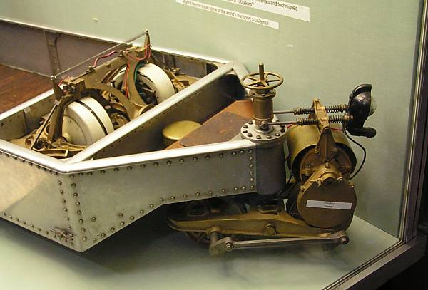
| Left: The Brennan model in the National Railway Museum at York.
This is the front end, with the two white gyroscopes at the left, and the geared traction motor at right. The white label says "Traction motor" but it is actually stuck on the reduction gear casing. The coupling rod between the two wheels can be clearly seen.
The thing at extreme right appears to be a headlight, mounted with horizontal springing, for some reason. It seems to be fitted in the picture of the model carrying Brennan's daughter. (above)
Once again the function of the handwheel above the motor pivot is unknown; possibly a friction damper.
Picture kindly provided by Stephen Holland.
|
BIBILIOGRAPHY:
"A full description of the mechanism, with a mathematical discussion on the subject, is given by Mr. H. Cousins in the issue of Engineering for Nov. 21st, 1913, and following numbers."
A good account of Brennan's monorail endeavours, and his other projects, such as helicopters, is given in a PhD thesis by Michael Kitson: "The Brennan Torpedo, Monorail, and Helicopter" There is a copy in the Science Museum Library, London: Dewey number 623.93
A good book on Brennan and his inventions is "Louis Brennan, Inventor Extraordinaire" by Norman Tomilinson, published in 1980 by John Hallewell Publications. ISBN 0 905540 18 2

LINKS
There is more information on the Brennan monorail here: absoluteastronomy.com.
There is more on the Brennan Torpedo at Wikipedia.

