This page is dedicated to amplifiers that are mostly mechanical, rather than those which are electric-in, electric out, such as the carbon-microphone repeaters used in the early days of telephony. These can now be found in the Electromechanical Amplifiers gallery.
THE HIGHAM FRICTIONAL AMPLIFIER FOR GRAMOPHONES
In 1901 Daniel Higham (pronounced hi-am) introduced the mechanical friction amplifier; see British patent number 13739. In 1904 he introduced the Higham-A-Phone reproducer, the design using a rosin wheel and friction shoe with a tensile link to the reproducing diaphragm giving effective mechanical amplification.
 |
| Left: The Higham Mechanical amplifier; taken from the diagrams in Patent 13739.
A is the input diaphragm, to which the needle is attached. This modulates the force with which lever D presses shoe L against the rotating friction wheel C. Shoe L moves back and forth in response to the varying friction, against the tension from output diaphragm B.
|
There was also an invention by G C Marks, apparently applicable to phonographs and telephone repeaters, which refers to Higham's 1901 patent. No further details available at present.
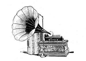 |
| Left: The Columbia Graphophone
The frictional amplifier is not visible here, as it is benind the diaphragm casing. The input diaphragm is replaced by a stylus bearing on the phongraph culinder.
The Columbia company bought up Higham's design in the same year of 1904, and used the amplifier technology in their top-of-the-line Twentieth Century Graphophone. This was produced from 1905 to 1908. Note that many Columbia's phonographs were called Graphophones, not just the mechanical-amplifier models.
You can hear a restored Graphophone on YouTube; it sounds rather better than you might expect. The horn is enormous and supported at its outer end by a metal stand. The clockwork motor is also of impressive size, mostly filling the lower cabinet.
|
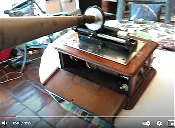 |
| Left: The Columbia Graphophone
The big drum containing the driving spring can just be seen. The winding handle is on the end of the box nearer the camera.
Source: YouTube 0:40
|
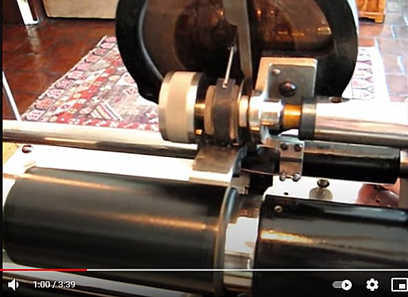 |
| Left: The Columbia Graphophone mechanical amplifier
The small grey roller with a white lever on top of it is the rotating cylinder shown in Higham's patent; the white lever is the equivalent of lever D. The roller goes round much more slowly than the wax cylinder. Note the loud saxophone noises as the machine gets up to speed.
Source: YouTube 1:00
|
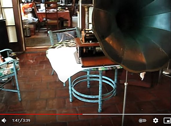 |
| Left: The Columbia Graphophone
This gives some idea of the size of the horn.
Source: YouTube 1:47
|

THE BROWN FRENOPHONE. 1922
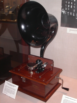 |
| Left: The Brown Frenophone, as displayed in The Science Museum, London: 1922
The Brown Frenophone was an electric-in, mechanical-out amplifier. Since its basic power source was clockwork, I decided it was mostly mechanical and belongs on this page.
This machine looks very much like an antique gramophone playing a very small disk, but it is actually nothing of the kind. The Frenophone was designed to amplify weak radio signals to loudspeaker volume, before it became technically or economically practical to do it with valves.
It did this by using a telephone receiver to modulate the friction between a small shoe and a glass disk rotated by clockwork. The shoe was held by two strings; one end of these terminated in a diaphragm at the throat of a conventional gramophone horn. The shoe was covered with a thin cork layer on its lower surface. The coefficient of friction of cork against glass is high, and this explains the high gain and volume that is reported to have been given by this loudspeaker. Nothing so far has been found about the quality of reproduction.
The handle on the side is for rewinding the clockwork motor.
|
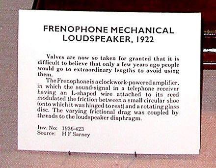 |
| Left: The official explanation of the method of operation of the Brown Frenophone, as displayed in the glass case
The only reference I have found to this technology was in the French journal "La Nature" in 1923, where it was described as "haut-parleur amplificateur, le frenophone". It is known to have been used by radio amateurs in 1924.
|
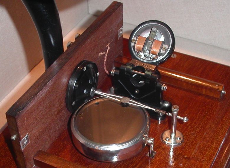 |
| Left: A close-up of the Frenophone mechanism.
The electro-magnetic receiver has been swivelled backwards to show the small circular shoe on its two supporting threads. The weight of the receiver was counterbalanced by a cylindrical weight when it was in the lowered (operating) position.
The diaphragm is inside the circular black metal housing to the left; it communicates with the horn through the wooden back-board.
|
|
| 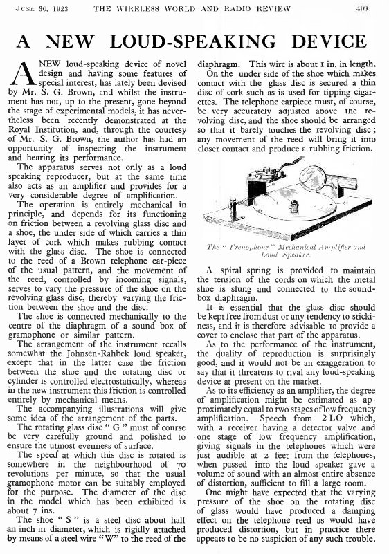 |
| Left: A Wireless World article on the Brown Frenophone: 1923
This sounds like a rather crude setup and I am surprised it worked as well as is reported here. Why was it introduced when by 1923 valve amplification
was well established? Perhaps because it was cheaper in first cost, perhaps because there was no need for filament accumulators that needed recharging, or HT batteries that were expensive.
Note the reference to the Johnsen-Rahbek loudspeaker, which sounds obscure indeed. Watch this space...
From Wireless World for 30 June 1923
|
TORQUE AMPLIFIERS
Frictional amplifiers can also be used to magnify torque rather than movement. The classic application was amplifying the very small torques produced by ball-and-disc integrators in mechanical differential analysers and gunnery computers.
See: Vannevar Bush's Differential Analyser. (external link)
You can of course make them out of Meccano: http://users.actcom.co.il/meccano/torqueamplifier.html


