III. Phonograms (Talking paper).
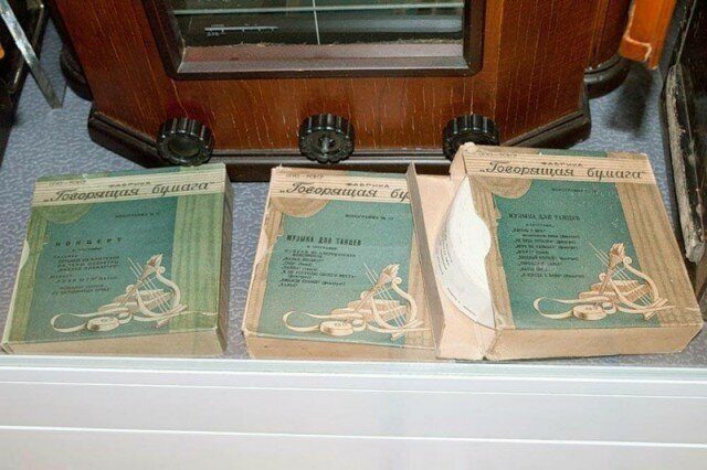
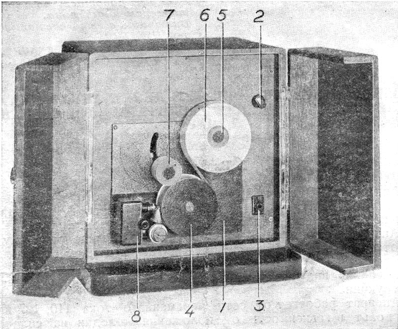
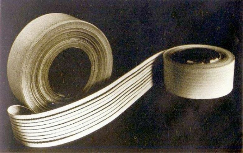
To reproduce sound in the device, a special phonogram is used, printed in a polygraphic way on a paper tape (Fig. 4). A tape 35 mm wide is wound on a cardboard ring with a slot. A strip of calico is glued to the free end of the tape, which serves to fix the tape on the coil 7 (Fig. 1) of the apparatus. The phonogram has eight audio tracks, on which the sound is recorded in different directions, i.e. if the first track goes from left to right, then the second track, which is a continuation of the first, goes from right to left, the third track goes from left to right, etc. Such an arrangement of the record makes it possible, with automatic switching of the tape drive mechanism, to obtain continuous sound for up to 45 minutes. The ordinal count of audio tracks is taken from the front extreme (track 1) to the back extreme (track VIII), if you hold the tape in front of you so that the roll unwinds when it is rotated counterclockwise. When rewinding the tape from reel 5 to reel 7 (Fig. 1), I, III, V and VII are played in turn, i.e. oddaudio tracks, and when the tape moves in the opposite direction (from reel 7 to reel 5), II, IV, VI and VII are played, i.e. even audio tracks. The content of the recording is listed on the outer end of each roll of tape.
IV. Turning on the device.
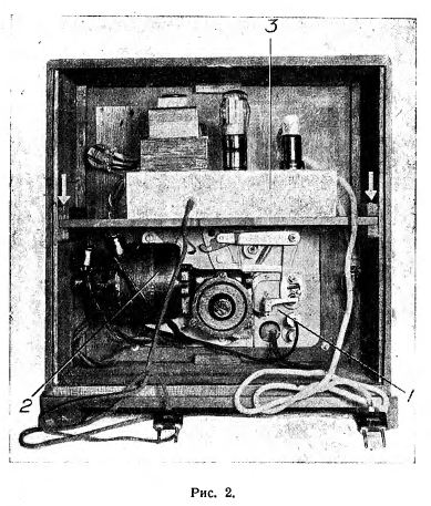
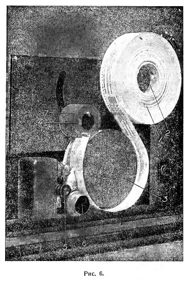
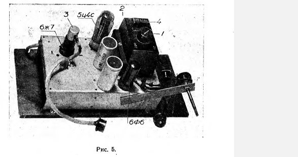
Before switching on the device, it is necessary to check whether the switching on of the device corresponds to the mains voltage. All devices manufactured from the factory are switched on for a voltage of 220 volts. The mains voltage can be found by the inscription on the meter or the base of the lighting lamps. If the mains voltage is 110 or 127 volts, then it is necessary to switch the transformer of the photoblock in accordance with the available voltage. To do this, take out the rear door of the device and unscrew the two screws that fasten the shelf with the photoblock installed on it to the box (the location of the screws is indicated in Fig. 2 by arrows). After that, the handle of switch 2 is pulled off the axis (Fig. 1), two connecting blocks are disconnected inside the device (located on the right and connecting the wires going from the photoblock to the mechanism) and then the shelf is pulled out of the box together with the photoblock. When the photoblock is taken out of the box, block 1 (Fig. 5) with an arrow located on power transformer 2 must be removed and installed in such a way that the arrow points to the number corresponding to the available mains voltage (the numbers are indicated on the transformer cover). The device is sold with a complete set of lamps, moreover, all lamps, including the photocell, are inserted into their sockets. On fig. 5 shows the photoblock taken out of the apparatus together with the shelf on which it is installed. Before switching on the device, it is useful to check whether all the lamps are firmly and correctly inserted into their respective sockets. It is also recommended to remove the shielding cap 3 from the lamp 6g7 and check the tightness of the contact cap on the lamp, then install the cap 3 in its place. You should also open the cap 6 (Fig. of the photocell was directed upwards and the contact bases of the photocell were tightly covered by the springs of the holders. After checking the tightness of the lamps, you need to slide the shelf with the photoblock into the box, turn on the connecting blocks according to the colors of the dots marked on the blocks (the dots should be located opposite each other) and put the switch knob 2 in its place (Fig. 1). Next, you need to install roll 1 (Fig. 6) with paper tape on the spool 2 of the device. In this case, the protrusion on the reel 2 should fall into the slot of the cardboard ring on which the tape is wound. To avoid displacement of the winding from the cardboard ring, when installing the tape on the machine, hold it with both hands. After that, you need to release the upper turn of the tapefrom the metal clip, circle the end of the tape around the drive drum 3 so that the tape lies between the sides of the drum and push its thickened end into the slot of the coil 4. Having fixed the end of the tape, it is necessary, by rotating the coil 4 counterclockwise, to tightly and evenly wind it 2- 3 turns. After making sure that switch 2 (Fig. 1) is turned off (the dot on the handle is opposite the leftmost point on the panel), you can plug the cord with the inscription "mains" on the plug into the AC power outlet. Then by setting the switch to the middle position, turn on the photoblock. It is impossible to turn on the photoblock if the tape is not installed on the device, because this can lead to damage to the device. , to the adapter jacks of the radio, previously connected to the AC mains. If a strong background (buzz) appears, it is necessary to remove the "exit" plug from the sockets of the receiver and, having swapped the legs of the plug, insert it again. After making sure that the device is turned on correctly, you need to disconnect it from the AC mains, fix the shelf (with the photoblock installed on it) with the previously removed screws, reinsert the rear door of the box and plug the device back into the AC mains. It must be remembered that after plugging the "mains" plug into the mains socket, the device is under current, therefore, in no case should you touch the parts of the device located inside the box. If necessary, manipulate these parts of the device (for example, to change the fuse, checking the fit of the lamps, etc.), you must first turn off the mains plug from the socket. After all the operations listed in this section have been completed, the device is ready for operation.
V. Apparatus management.
After the above preparation, you can turn on the motor by turning switch 2 (Fig. 1) to the extreme right position. To play a phonogram from the beginning of the recording, it is necessary to install the movable optics carriage against the first sound track; for this, the movable carriage is manually extended towards itself until it fails. Pulling out the carriage must always be done by the handle 5 (Fig. 6). After the end of playing one audio track, the tape drive mechanism automatically switches and the tape begins to be pulled in the opposite direction. At the same time, the carriage automatically moves to the next audio track. After playing all eight tracks, the motor also automatically turns off. If you want to repeat one of the played audio tracks, you need to push the movable optics carriage towards you and set it against the desired audio track. If the carriage is not installed on the desired track, it is necessary to move the carriage forward one track and then push it back by briefly pressing the button 3 (Fig. 1) for switching from track to track. The jump button can only be used while the tape is moving. Keeping the button pressed for a long time can damage the mechanism. It must be remembered that frequent and aimless use of the transition button adversely affects the operation of the mechanism and leads to increased wear of the tapes. Before removing the listened tape from the device, regardless of whether the mechanism stopped itself, i.e. automatically (in case the previous tape was listened to to the very end), or it was stopped using switch 2 (Fig. 1), - it is necessary to turn off the photo block by moving the switch to the left position, because otherwise the device can be damaged. If you want to change the tape roll before the end of playing all eight audio tracks, turn off the motor and photoblock (by moving the switch to the left position) at the moment when the tape is wound on reel 2 (Fig. 6). It is possible to put on a new tape and take off a listened tape only from the right spool 2. The tape roll removed from the device should be fastened with a metal clip (attached to the tape). To install a new roll of ribbon on the machine, see "Turning on the Machine". The volume and tone of the sound are adjusted by the corresponding knobs of the radio receiver. When playing tapes, it is recommended to close the drawer doors.
4. Care of the device.
Storage conditions.
When the machine is not working, switch 2 (Fig. 1) must be turned off and the drawer doors closed. The device must be protected from moisture and dust. Its storage near heating devices (stoves, radiators, etc.) is also not recommended.
Cleaning the photocell and microlens from dust.
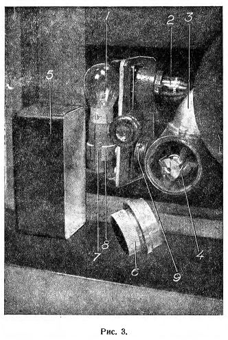
During the operation of the apparatus, the tape emits paper and chalk dust, which is deposited on the photocell and the front lens of the cylindrical microobjective. This leads to a weakening of the sound power. Removal of dust from the surface of the photocell and the lens of the microobjective should be carried out as needed, approximately every 30-40 hours of operation of the device. To clean the photocell, remove the cap 6 (Fig. 6), remove it and wipe it with a clean soft clothphotocell. When reinstalling the photocell, the thicker (or longer) contact base is pushed deep into the camera, making sure that the transparent part of the photocell is directed upwards, after which it is closed with cap 2. Removing dust from the front surface of the front lens of the microlens should be done with a piece of dry gauze screwed on on a match, followed by blowing the place of rubbing. 3. Changing the illumination lamp. If the illuminating lamp 1 burns out (Fig. 3), it is necessary to remove the casing 5 that covers the lamp, turn the lamp and remove it from the socket 7. When installing a new lamp, it is necessary to adjust its position. The lamp filament should be located perpendicular to the plane of the panel and set against the center of the cylindrical microobjective (the first is achieved by turning the cartridge with the light bulb, and the second - by longitudinal movement of the cartridge 7 in the collar 8). Next, slightly loosen screw 9 and, while playing the tape on the device, tilt the cartridge with the lamp in different directions until you find the position at which you get the maximum volume and the best sound clarity. In this position, you need to fix the illuminating lamp by tightening the screw 9, then put the casing 5 in its place. A spare lamp is included with the device. 4. Change the fuse. The photoblock and the motor of the device are protected by a tubular fuse 4 (Fig. 5) of 1.5 amperes (the fuse is the same as for the 6N-1 receiver) installed on the transformer 2 of the photoblock. If a fuse blows, it must be replaced. To do this, you need to remove the photoblock from the device (using the method described in the "switching on the device" section) and remove the cover that protects the fuse from mechanical damage. A spare fuse is included with the device. After changing the fuse, the protective cover must be replaced.
5. Transportation.
The device is a stationary device and its transportation requires some care. Before transporting the device, it is necessary to check whether the shelf with the photoblock is firmly fixed with screws. Any movement can only be carried out with the apparatus in a vertical position. Also, do not turn the device upside down, as this can lead to damage. It must also be taken into account that shocks and blows are harmful to the apparatus.
VII. Rules for the use of tapes.
Storage.
Tape storage in obviously damp or wet place is unacceptable. Storage of tapes at elevated temperatures (near stoves, radiators, etc.) is also undesirable. Tapes should be stored in the boxes intended for them.
2. Gluing.
In the event of a break or sticking of the tape, it is necessary to remove it from the device and glue it together. The tape is removed from the device together with the coil 4 (Fig. 6), for which, pressing the latch 7 with your finger, tighten the coil 4 with both hands. From reel 2, the tape is removed in the usual manner. The broken ends of the tape are trimmed with scissors, after which one of them is smeared with glue (syndeticone, photo glue, gum arabic, etc.) at a distance of 3-4 millimeters from the end and carefully superimposed on the other. The adhesive is pressed tightly with the fingers. Care must be taken to ensure that the tapes to be glued are superimposed one on top of the other without lateral shift.
VIII. The main faults, their causes and elimination.
If certain malfunctions appear, you must first make sure that the radio receiver with which the device works is in good condition, which can be done either by checking the quality of the receiver for playing gramophone records with an adapter, or by replacing the receiver with another serviceable receiver. After making sure that the receiver is in good condition, they begin to search for the causes of malfunctions of the device itself. Below is a list of the main faults, which do not require special qualifications to eliminate. Using this list, you should check in the sequence of the list. Example. When looking for the reasons for the absence of sound, you must first check whether the motor is running and whether the backlight lamp is on, and then check the reasons for the absence of sound, in the order in which they are presented. In this case, you should not proceed to the next stage of the test without eliminating the previously found faults."
|