Gallery opened 30 June 2018
Updated: 7 July 2018
Vanni hydraulic microphone added
Microphone history added


Hydraulic Microphones |
Gallery opened 30 June 2018 |
In the early days of radio, continuous-wave transmission suitable for voice communication could not be generated by valves as suitable types had not yet been developed. A continuous-wave carrier could be produced by Duddel's singing arc, or Fessenden's high-frequency (50 kHz) alternators. The only way to modulate audio frequencies onto the carrier was to pass the whole of the antenna current through a carbon microphone or equivalent. These naturally got very hot and water-cooled carbon microphones were used; given the heat and also the high voltages used, early broadcasters probably approached their microphones with some trepidation. A similiar approach was used in the Tannoy power microphone in 1937.
A lesser-known alternative was the application of hydraulics to microphones; at least two models of hydraulic microphone were produced in Italy in the 1900's.
A BRIEF HISTORY OF MICROPHONES
The first microphone was invented by the German Johann Philipp Reis. This had a flexible diaphragm connected to a metallic strip that made and broke contact. This was only capable of transmitting OFF or ON unless you could be sure of some sort of partial contact. This did not necessarily make it unworkable- the speech signal is very robust. For example, you can send perfectly understandable speech by just transmitting a click at each zero-crossing of the waveform. However the Reis device pushed this too far and it was not capable of reproducing understandable speech.
The first practical microphone was the carbon type invented by both David Edward Hughes and Edison in 1878, which was developed to give adequate audio quality.
There is some stuff on microphone history in Wikipedia.
THE MAJORANA HYDRAULIC MICROPHONE
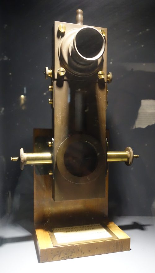 | Left: The Majorana hydraulic microphone: 1909
|
 | Left: The Majorana hydraulic microphone: 1901
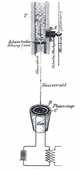
achatscheibe = agate slice. (Presumably this describes an agate nozzle) offnung = opening. (1mm diameter) glasrohre = glass tube. The date indicates that Majorana's microphone was around long before its use in long-distance telephony in Italy in 1906. |
THE VANNI HYDRAULIC MICROPHONE
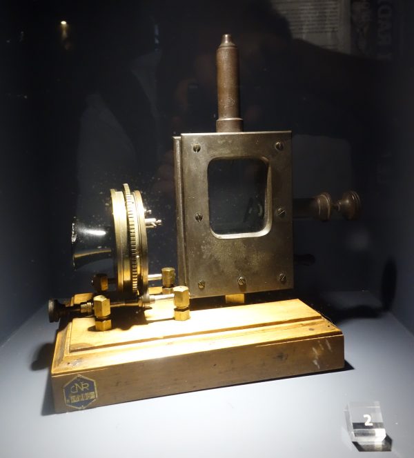 | Left: The Vanni hydraulic microphone: 1912
|
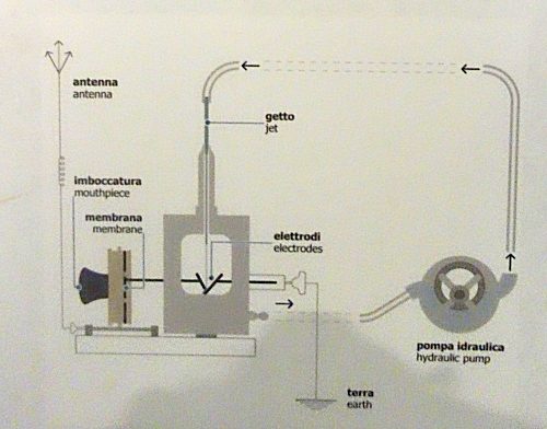 | Left: The Vanni hydraulic microphone: 1912
|
![]()

|